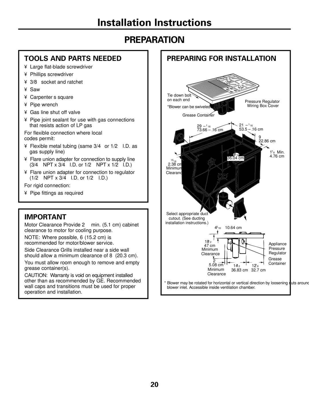
JGP990 specifications
The GE JGP990 is a high-performance gas range that stands out for its innovative features, robust construction, and impressive cooking capabilities. As part of General Electric's profile line, the JGP990 reflects the brand's legacy of quality and reliability while incorporating modern technologies that cater to the needs of today's home cooks.At the forefront of the JGP990's features is its five-burner cooking surface, which includes a powerful 21,000 BTU tri-ring burner. This burner allows for versatile cooking techniques, from rapid boiling to gentle simmering. With multiple burner sizes, users can easily adjust the heat to accommodate various pot sizes and cooking methods. Furthermore, the continuous grates provide a seamless surface that allows for easy movement of pots and pans across the burners, enhancing convenience and efficiency.
In addition to its impressive burner options, the GE JGP990 is equipped with a built-in electric ignition system, providing reliable and easy start-up. This system eliminates the need for matches or lighters, allowing for a hassle-free cooking experience. The range also features heavy-duty cast iron grates that are not only durable but also add an element of professional-grade quality to the kitchen.
One of the standout features of the GE JGP990 is its integrated oven, which utilizes a powerful convection cooking system. This technology ensures even heat distribution, resulting in perfectly cooked meals, whether baking or roasting. The oven's self-cleaning mode simplifies maintenance, allowing users to spend less time scrubbing and more time enjoying their culinary creations.
The design of the JGP990 is equally impressive, available in stylish finishes that fit seamlessly into contemporary kitchens. The sleek stainless steel exterior not only enhances the aesthetic appeal but is also easy to clean, making it perfect for busy households.
Safety is paramount in the design of the GE JGP990, which includes features such as control lock and automatic shut-off. These elements provide peace of mind, especially for families with children.
Overall, the GE JGP990 gas range is a harmonious blend of power, versatility, and style, making it an ideal choice for both amateur cooks and professional chefs alike. Its cutting-edge features, reliable performance, and thoughtful design position it as a standout appliance in the ever-evolving culinary landscape.

