Section 5.2

ENGINE COOLING SYSTEM

It is absolutely essential that an adequate flow of air for cooling, ventilating and engine combustion be sup- plied to the generator set. Without sufficient air flow, the engine-generator quickly overheats. Such over- heating can cause serious operating difficulties and may also cause fire and personal injury. The installer must make sure that sufficient air is available to the generator for cooling, ventilating and combustion. The installer must also provide for a path for exhausting the cooling air to the exterior of a compartment, if so equipped.

DANGER: Never use discharged cooling air for heating or permit such air to enter the

vehicle interior. This air contains deadly car- bon monoxide gas and other poisonous, flammable or explosive gases.

GENERATOR AIR FLOW

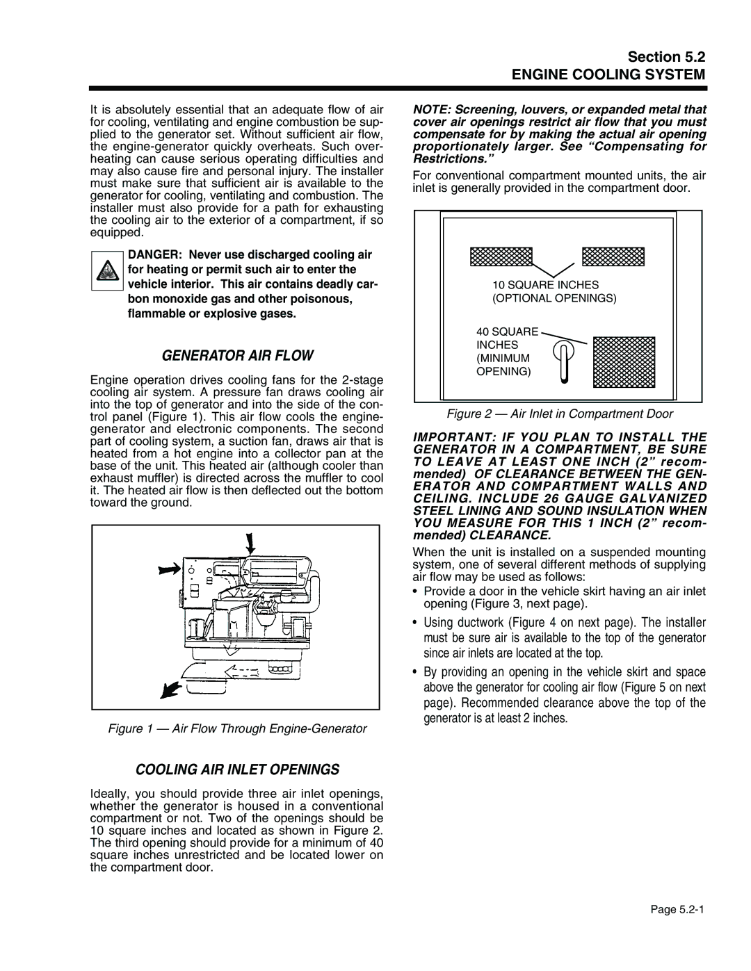
Engine operation drives cooling fans for the 2-stage cooling air system. A pressure fan draws cooling air into the top of generator and into the side of the con- trol panel (Figure 1). This air flow cools the engine- generator and electronic components. The second part of cooling system, a suction fan, draws air that is heated from a hot engine into a collector pan at the base of the unit. This heated air (although cooler than exhaust muffler) is directed across the muffler to cool it. The heated air flow is then deflected out the bottom toward the ground.

Figure 1 — Air Flow Through Engine-Generator

COOLING AIR INLET OPENINGS

Ideally, you should provide three air inlet openings, whether the generator is housed in a conventional compartment or not. Two of the openings should be 10 square inches and located as shown in Figure 2. The third opening should provide for a minimum of 40 square inches unrestricted and be located lower on the compartment door.

NOTE: Screening, louvers, or expanded metal that cover air openings restrict air flow that you must compensate for by making the actual air opening proportionately larger. See “Compensating for Restrictions.”

For conventional compartment mounted units, the air inlet is generally provided in the compartment door.

10 SQUARE INCHES

(OPTIONAL OPENINGS)

40 SQUARE

INCHES

(MINIMUM

OPENING)

Figure 2 — Air Inlet in Compartment Door

IMPORTANT: IF YOU PLAN TO INSTALL THE GENERATOR IN A COMPARTMENT, BE SURE TO LEAVE AT LEAST ONE INCH (2” recom- mended) OF CLEARANCE BETWEEN THE GEN-

ERATOR AND COMPARTMENT WALLS AND CEILING. INCLUDE 26 GAUGE GALVANIZED STEEL LINING AND SOUND INSULATION WHEN YOU MEASURE FOR THIS 1 INCH (2” recom- mended) CLEARANCE.

When the unit is installed on a suspended mounting system, one of several different methods of supplying air flow may be used as follows:

Provide a door in the vehicle skirt having an air inlet opening (Figure 3, next page).

Using ductwork (Figure 4 on next page). The installer must be sure air is available to the top of the generator since air inlets are located at the top.

By providing an opening in the vehicle skirt and space above the generator for cooling air flow (Figure 5 on next page). Recommended clearance above the top of the generator is at least 2 inches.

Page 5.2-1

Page 87
Image 87
Generac Power Systems 941-2, 940-2 service manual Generator AIR Flow, Cooling AIR Inlet Openings

941-2, 940-2 specifications

Generac Power Systems has established a strong reputation in the field of backup power solutions, particularly with its innovative products like the Generac 940-2 and 941-2 generator systems. These generators are designed to provide reliable power during emergencies, ensuring that homes and businesses can maintain operations seamlessly when grid power is disrupted.

One of the standout features of the Generac 940-2 and 941-2 models is their robust engine performance. Both generators utilize Generac’s patented engines, known for their durability and efficiency. These engines are built to withstand the most demanding conditions while providing a consistent power output. This reliability is crucial for users who depend on uninterrupted power supply for essential appliances and equipment.

In terms of technologies, the Generac 940-2 and 941-2 are equipped with advanced automatic transfer switch capabilities. This technology allows the generators to automatically start and supply power within seconds of an outage. This quick response time helps to ensure that critical systems remain operational without noticeable interruptions, which is vital for businesses and households alike.

Another important characteristic of these models is their user-friendly interface. The generators come with an intuitive digital controller that provides real-time information on power usage, system status, and maintenance needs. This technology makes it easy for users to monitor their generators and ensure they are always ready for an emergency.

The design of the Generac 940-2 and 941-2 also emphasizes noise reduction and aesthetic appeal. These units are engineered for quieter operation compared to traditional generators, making them suitable for residential areas. Their sleek appearance also fits well with modern home exteriors, enhancing rather than detracting from the property’s visual appeal.

Furthermore, these generators offer flexible fuel options, with the ability to run on natural gas or propane. This versatility allows users to choose the fuel source that best meets their needs, contributing to energy efficiency and lowering overall operating costs.

In summary, the Generac Power Systems 940-2 and 941-2 are exceptional generators that combine powerful performance with innovative technologies. Their automatic transfer switch capabilities, user-friendly controls, noise reduction features, and flexible fuel options make them an excellent choice for anyone seeking reliable backup power solutions. With these generators, users can rest assured knowing they have a dependable energy source ready when they need it most.