Part 8

SPECIFICATIONS & CHARTS

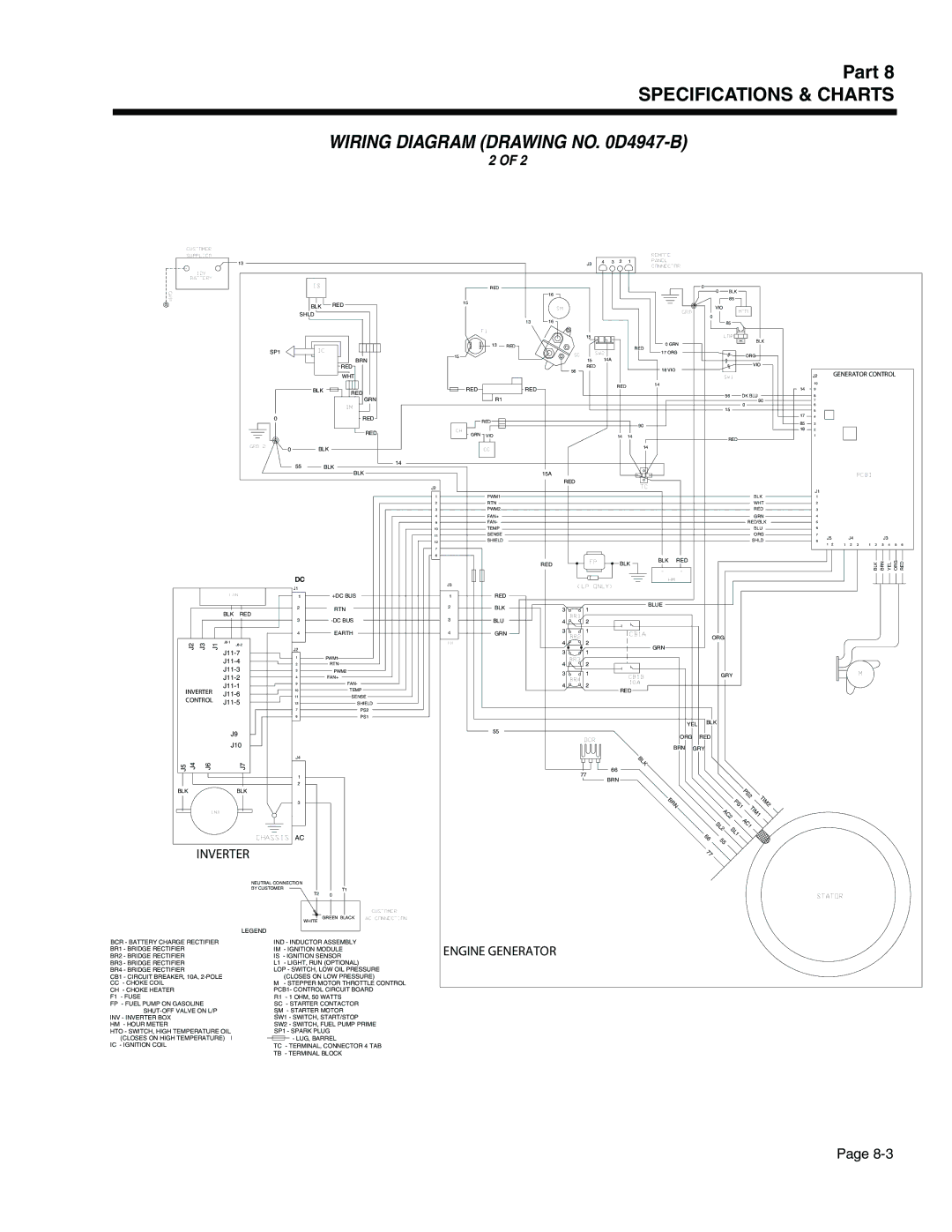
WIRING DIAGRAM (DRAWING NO. 0D4947-B)

2 OF 2

CUSTOMER

SUPPLIED

13

12V BATTERY

IS

GRD

BLK RED

SHLD

SP1IC

BRN

RED

WHT


BLK

RED


GRN


IM


0


RED


RED

GRD 2

0

BLK


55

BLK

14


REMOTE


J3

4

3 2 1

PANEL


CONNECTOR


RED


0

BLK


16


0


85

15


VIO


SM


HTO


GRD


0


13

16


85

F1

15LOP


13 RED


0 GRN

BLK


RED


15

SC

SW2


17 ORG

ORG

14A


15


VIO


RED


18 VIO


56


SW1


RED

RED


RED

14


R1


56

DK BLU


90


15

0


RED


90


CH


GRN

VIO


14

14


RED


CC

14

J2 GENERATOR CONTROL

10

149

8

7

6

5

174

853

182

1

BLK

J2

1PWM1

2RTN

3PWM2

4FAN+

9FAN-

10TEMP

11SENSE

12SHIELD

7

6

15A

RED

TC

BLK

WHT

RED

GRN

RED/BLK

BLU

ORG

SHLD

PCB1

J1

1

2


3


4


5


6


7


J4


J3


J5


8


1

2

1

2

3

1

2

3

4

5

6


FAN


BLK RED


J2

J3

J1

J8-1


J8-2


J11-7


J11-4


J11-3


J11-2


INVERTER


J11-1


J11-6


CONTROL

J11-5


J9


J10


J5

J4

J6


J7


BLK


BLK


IND

DC

J1

1+DC BUS

2RTN

3-DC BUS

4EARTH

J2

1PWM1

2RTN

3PWM2

4FAN+

9FAN-

10TEMP

11SENSE

12SHIELD

7PS2

6PS1

J4

1

2

3

J3

1RED

2BLK

3BLU

4GRN

TB

55

RED

FP

BLK

BLK

RED


-

+


HM


(LP ONLY)


BLUE

31

BR1

42

3

1

CB1A


BR2


ORG


4 2

GRN

31

BR3

42

3

1

CB1B


GRY


BR4


10A


4

2


RED


YEL

BLK


BCR

ORG


RED


BRN

GRY


BLK


77

66


BRN


PS2

T


BRN


P


IM


S1


2


TIM


AC2


1


S


AC1


L


2

SL


1


BLK

BRN

YEL

ORG

RED

M

CHASSIS AC

INVERTER

66

55

77

BCR - BATTERY CHARGE RECTIFIER BR1 - BRIDGE RECTIFIER

BR2 - BRIDGE RECTIFIER

BR3 - BRIDGE RECTIFIER

BR4 - BRIDGE RECTIFIER

CB1 - CIRCUIT BREAKER, 10A, 2-POLE

CC- CHOKE COIL CH - CHOKE HEATER F1 - FUSE

FP - FUEL PUMP ON GASOLINE SHUT-OFF VALVE ON L/P

INV - INVERTER BOX HM - HOUR METER

HTO - SWITCH, HIGH TEMPERATURE OIL (CLOSES ON HIGH TEMPERATURE)

IC - IGNITION COIL

NEUTRAL CONNECTION


BY CUSTOMER

T1

T2

0


CUSTOMER

GREEN BLACK

AC CONNECTION

WHITE


LEGEND

IND - INDUCTOR ASSEMBLY IM - IGNITION MODULE

IS - IGNITION SENSOR

L1 - LIGHT, RUN (OPTIONAL)

LOP - SWITCH, LOW OIL PRESSURE (CLOSES ON LOW PRESSURE)

M- STEPPER MOTOR THROTTLE CONTROL PCB1- CONTROL CIRCUIT BOARD

R1 - 1 OHM, 50 WATTS

SC - STARTER CONTACTOR SM - STARTER MOTOR SW1 - SWITCH, START/STOP

SW2 - SWITCH, FUEL PUMP PRIME SP1 - SPARK PLUG

- LUG, BARREL

TC - TERMINAL, CONNECTOR 4 TAB

TB - TERMINAL BLOCK

ENGINE GENERATOR

STATOR

Page 8-3

Page 135
Image 135
Generac Power Systems 941-2, 940-2 service manual Wiring Diagram Drawing no D4947-B, J2 Generator Control

941-2, 940-2 specifications

Generac Power Systems has established a strong reputation in the field of backup power solutions, particularly with its innovative products like the Generac 940-2 and 941-2 generator systems. These generators are designed to provide reliable power during emergencies, ensuring that homes and businesses can maintain operations seamlessly when grid power is disrupted.

One of the standout features of the Generac 940-2 and 941-2 models is their robust engine performance. Both generators utilize Generac’s patented engines, known for their durability and efficiency. These engines are built to withstand the most demanding conditions while providing a consistent power output. This reliability is crucial for users who depend on uninterrupted power supply for essential appliances and equipment.

In terms of technologies, the Generac 940-2 and 941-2 are equipped with advanced automatic transfer switch capabilities. This technology allows the generators to automatically start and supply power within seconds of an outage. This quick response time helps to ensure that critical systems remain operational without noticeable interruptions, which is vital for businesses and households alike.

Another important characteristic of these models is their user-friendly interface. The generators come with an intuitive digital controller that provides real-time information on power usage, system status, and maintenance needs. This technology makes it easy for users to monitor their generators and ensure they are always ready for an emergency.

The design of the Generac 940-2 and 941-2 also emphasizes noise reduction and aesthetic appeal. These units are engineered for quieter operation compared to traditional generators, making them suitable for residential areas. Their sleek appearance also fits well with modern home exteriors, enhancing rather than detracting from the property’s visual appeal.

Furthermore, these generators offer flexible fuel options, with the ability to run on natural gas or propane. This versatility allows users to choose the fuel source that best meets their needs, contributing to energy efficiency and lowering overall operating costs.

In summary, the Generac Power Systems 940-2 and 941-2 are exceptional generators that combine powerful performance with innovative technologies. Their automatic transfer switch capabilities, user-friendly controls, noise reduction features, and flexible fuel options make them an excellent choice for anyone seeking reliable backup power solutions. With these generators, users can rest assured knowing they have a dependable energy source ready when they need it most.