2 – Standard Run 3 Wire Mode
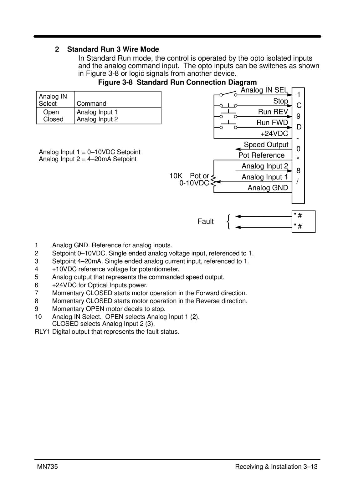
In Standard Run mode, the control is operated by the opto isolated inputs and the analog command input. The opto inputs can be switches as shown in Figure
Figure 3-8 Standard Run Connection Diagram
Analog IN |
|
Select | Command |
Open | Analog Input 1 |
Closed | Analog Input 2 |
|
|
Analog Input 1 =
Analog IN SEL
Stop
Run REV
Run FWD
+24VDC
Speed Output
Pot Reference
10
9
8
7
6
5
4
| Analog Input 2 |
10KW Pot or | Analog Input 1 |
Analog GND | |
| |
Fault |
|
3
2
1
RLY1A
RLY1B
1Analog GND. Reference for analog inputs.
2Setpoint
3Setpoint
4+10VDC reference voltage for potentiometer.
5Analog output that represents the commanded speed output.
6+24VDC for Optical Inputs power.
7Momentary CLOSED starts motor operation in the Forward direction.
8Momentary CLOSED starts motor operation in the Reverse direction.
9Momentary OPEN motor decels to stop.
10Analog IN Select. OPEN selects Analog Input 1 (2). CLOSED selects Analog Input 2 (3).
RLY1 Digital output that represents the fault status.
MN735 | Receiving & Installation |
