|
|
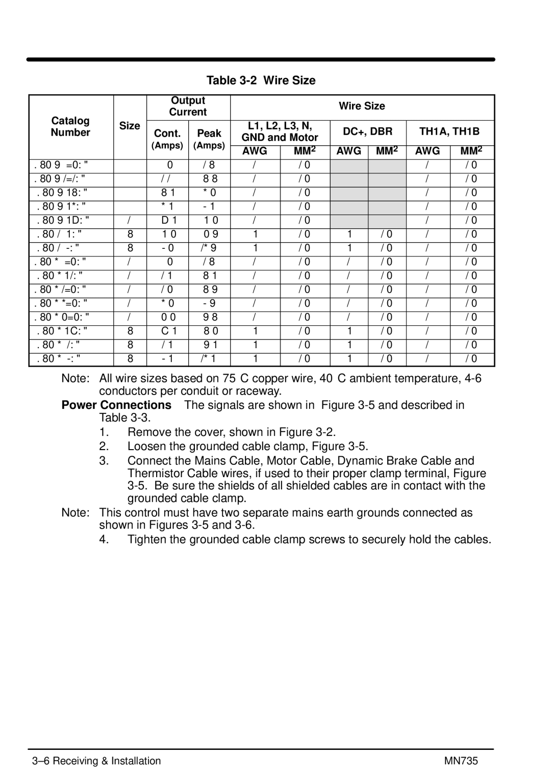
| Table |
|
|
|
| |||
|
|
|
|
|
|
|
|
|
| |
|
| Output |
|
| Wire Size |
|
| |||
|
| Current |
|
|
|
| ||||
Catalog |
|
|
|
|
|
|
| |||
|
|
|
|
|
|
|
|
| ||
Size |
|
| L1, L2, L3, N, | DC+, DBR | TH1A, TH1B | |||||
Number | Cont. | Peak | ||||||||
| GND and Motor | |||||||||
|
| (Amps) | (Amps) |
|
|
|
| |||
|
|
|
|
|
|
|
| |||
|
|
|
| AWG | MM2 | AWG | MM2 | AWG | MM2 | |
1 | 1.5 | 2.3 | 12 | 2.5 |
|
| 12 | 2.5 | ||
1 | 2.2 | 3.3 | 12 | 2.5 |
|
| 12 | 2.5 | ||
1 | 3.0 | 4.5 | 12 | 2.5 |
|
| 12 | 2.5 | ||
1 | 4.0 | 6.0 | 12 | 2.5 |
|
| 12 | 2.5 | ||
2 | 7.0 | 10.5 | 12 | 2.5 |
|
| 12 | 2.5 | ||
3 | 10.5 | 15.8 | 10 | 2.5 | 10 | 2.5 | 12 | 2.5 | ||
|
|
|
|
|
|
|
|
|
| |
3 | 16.5 | 24.8 | 10 | 2.5 | 10 | 2.5 | 12 | 2.5 | ||
|
|
|
|
|
|
|
|
|
| |
2 | 1.5 | 2.3 | 12 | 2.5 | 12 | 2.5 | 12 | 2.5 | ||
|
|
|
|
|
|
|
|
|
| |
2 | 2.0 | 3.0 | 12 | 2.5 | 12 | 2.5 | 12 | 2.5 | ||
|
|
|
|
|
|
|
|
|
| |
2 | 2.5 | 3.8 | 12 | 2.5 | 12 | 2.5 | 12 | 2.5 | ||
|
|
|
|
|
|
|
|
|
| |
2 | 4.5 | 6.8 | 12 | 2.5 | 12 | 2.5 | 12 | 2.5 | ||
|
|
|
|
|
|
|
|
|
| |
2 | 5.5 | 8.3 | 12 | 2.5 | 12 | 2.5 | 12 | 2.5 | ||
|
|
|
|
|
|
|
|
|
| |
3 | 9.0 | 13.5 | 10 | 2.5 | 10 | 2.5 | 12 | 2.5 | ||
|
|
|
|
|
|
|
|
|
| |
3 | 12.0 | 18.0 | 10 | 2.5 | 10 | 2.5 | 12 | 2.5 | ||
|
|
|
|
|
|
|
|
|
| |
3 | 16.0 | 24.0 | 10 | 2.5 | 10 | 2.5 | 12 | 2.5 | ||
Note: All wire sizes based on 75° C copper wire, 40° C ambient temperature,
Power Connections The signals are shown in Figure
1.Remove the cover, shown in Figure
2.Loosen the grounded cable clamp, Figure
3.Connect the Mains Cable, Motor Cable, Dynamic Brake Cable and Thermistor Cable wires, if used to their proper clamp terminal, Figure
Note: This control must have two separate mains earth grounds connected as shown in Figures
4.Tighten the grounded cable clamp screws to securely hold the cables.
MN735 |