Parameter Definitions You can program the Inverter for specific applications. The Inverter is supplied with
Note: Motor parameters are not changed when a new application is loaded.
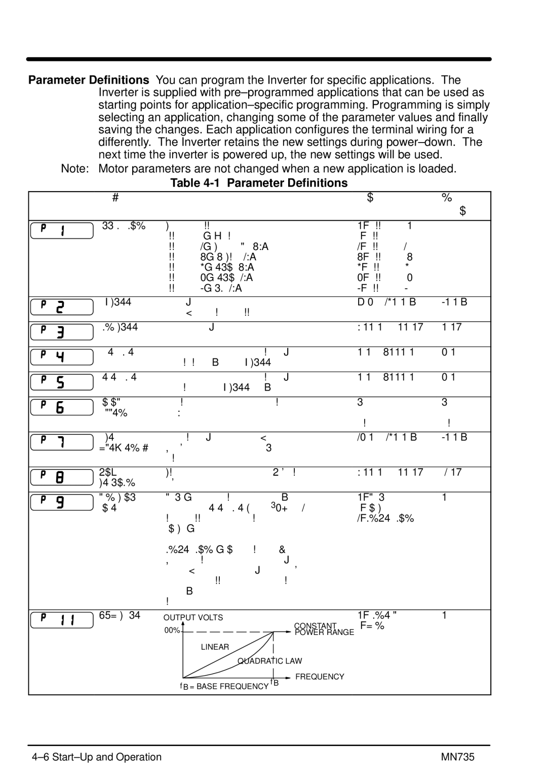
Table 4-1 Parameter Definitions
Display | Parameter | Description | Range | Factory |
|
|
|
| Setting |
| APPLICATION | Selects the applicaton to be used | 0= Application 0 | 1 |
|
| Application 1: Keypad mode | 1= Application 1 |
|
|
| Application 2: Standard Run | 2= Application 2 |
|
|
| Application 3: 3 Speed | 3= Application 3 |
|
|
| Application 4: EPOT | 4= Application 4 |
|
|
| Application 5: EPOT | 5= Application 5 |
|
|
| Application 6: PID | 6= Application 6 |
|
| MAX SPEED | The frequency at which the control will run | 7.5 to 240.0Hz | 60.0Hz |
|
| when maximum setpoint is applied |
|
|
| MIN SPEED | The minimum frequency at which the control will | 0.0% | |
|
| run. |
|
|
| ACCEL TIME | The time taken for the control output frequency | 0.0 to 3000.0s | 5.0s |
|
| to ramp up from zero to MAX SPEED |
|
|
| DECEL TIME | The time taken for the control output frequency | 0.0 to 3000.0s | 5.0s |
|
| to ramp down from MAX SPEED to zero |
|
|
| MOTOR | This parameter contains the motor nameplate | Product | Product |
| CURRENT | code | code | |
|
|
| dependent | dependent |
| BASE | The output frequency at which maximum | 25.0 to 240.0Hz | 60.0Hz |
| FREQUENCY | voltage is reached. The default is Product Code |
|
|
|
| dependent. |
|
|
| JOG | Speed the control will run at if the Jog input is | 12.0% | |
| SETPOINT | high |
|
|
| RUN STOP | RAMP : The motor speed is reduced to zero at | 0=RAMP | 0 |
| MODE | a rate set by DECEL TIME (P5). A 2 second | 1=COAST |
|
|
| pulse is applied at end of ramp | 2=INJECTION |
|
|
| COAST : The motor is allowed to freewheel to a |
|
|
|
| standstill |
|
|
|
| INJECTION : On a stop command, the motor |
|
|
volts are rapidly reduced at constant frequency to deflux the motor. A low frequency braking current is then applied until the motor speed is almost zero. This is followed by a timed DC pulse to hold the motor shaft.
V/F SHAPE | OUTPUT VOLTS | 0=LINEAR | 0 | |
| 00% | CONSTANT | 1=FAN |
|
| POWER RANGE |
|
| |
|
|
|
| |
|
| LINEAR |
|
|
|
| QUADRATIC LAW |
|
|
|
| FREQUENCY |
|
|
|
| f B = BASE FREQUENCY f B |
|
|
MN735 |