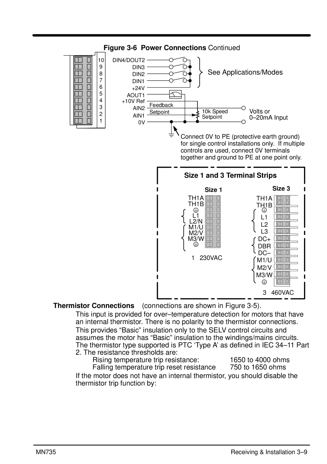
Figure 3-6 Power Connections Continued
10 | DIN4/DOUT2 |
|
|
| |
9 | DIN3 |
| See Applications/Modes | ||
8 | DIN2 |
| |||
7 | DIN1 |
|
|
| |
6 | +24V |
|
|
| |
5 | AOUT1 |
|
|
| |
4 |
|
|
| ||
+10V Ref | Feedback |
|
| ||
3 |
|
| |||
AIN2 | Setpoint | 10k Speed | Volts or | ||
2 | |||||
AIN1 |
| Setpoint | |||
1 |
| ||||
0V |
|
|
| ||
|
|
|
| ||
Connect 0V to PE (protective earth ground) for single control installations only. If multiple controls are used, connect 0V terminals together and ground to PE at one point only.
Size 1 and 3 Terminal Strips
| Size 1 |
| |
| TH1A |
| |
| TH1B |
| |
AC | L1 |
| |
Line | AC Line | ||
L2/N | |||
|
| ||
| M1/U |
| |
Motor | M2/V |
| |
M3/W | Dynamic | ||
|
| ||
|
| Brake | |
| 1φ 230VAC |
| |
|
| Motor |
Size 3
TH1A
TH1B
L1
L2
L3
DC+ ![]()
![]()
![]()
![]()
![]()
DBR DC– M1/U M2/V M3/W
3φ 460VAC
Thermistor Connections (connections are shown in Figure 3-5).
This input is provided for
2. The resistance thresholds are:
Rising temperature trip resistance: | 1650 to 4000 ohms |
Falling temperature trip reset resistance | 750 to 1650 ohms |
If the motor does not have an internal thermistor, you should disable the thermistor trip function by:
MN735 | Receiving & Installation |
