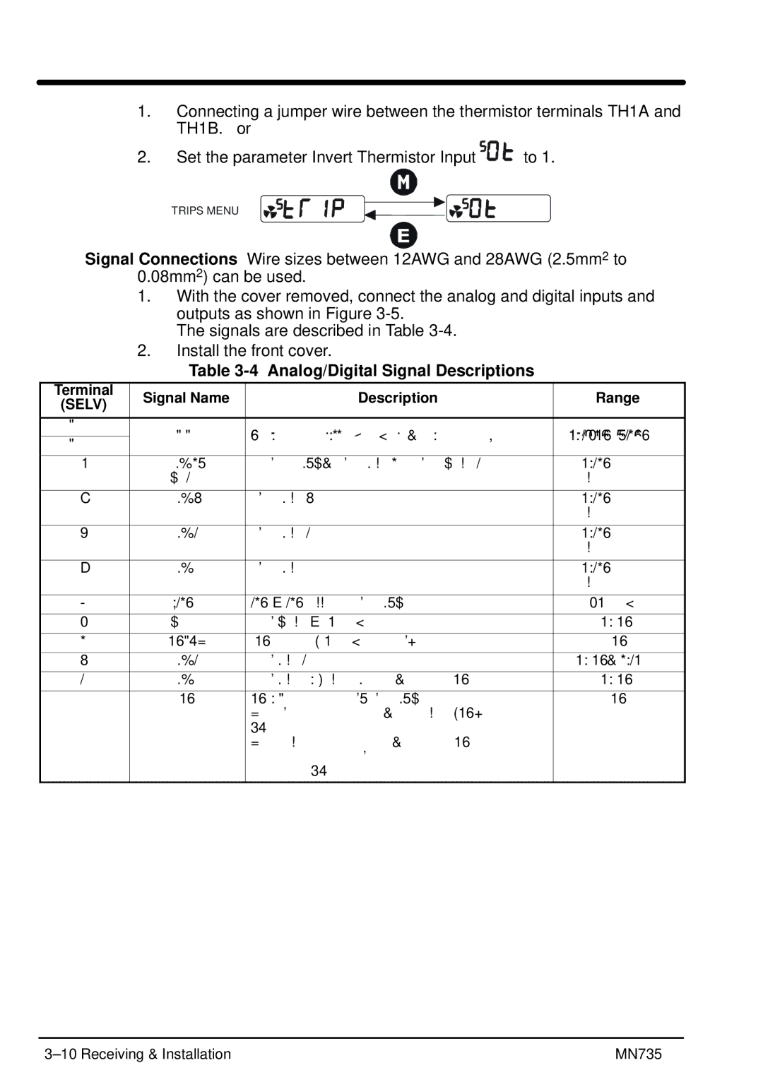
1.Connecting a jumper wire between the thermistor terminals TH1A and TH1B. or
2.Set the parameter Invert Thermistor Input ![]()
![]()
![]()
![]() to 1.
to 1.
TRIPS MENU
Signal Connections Wire sizes between 12AWG and 28AWG (2.5mm2 to 0.08mm2) can be used.
1.With the cover removed, connect the analog and digital inputs and outputs as shown in Figure
The signals are described in Table
2.Install the front cover.
Table 3-4 Analog/Digital Signal Descriptions
Terminal | Signal Name | Description | Range | |
(SELV) | ||||
|
|
| ||
|
|
|
| |
RL1A | User Relay |
| ||
| ||||
RL1B | ||||
|
|
| ||
|
|
|
| |
10 | DIN4/ | Configurable I/O, Digital Input 4 or Digital Output 2. | ||
| DOUT2 |
| open collector | |
|
|
|
| |
9 | DIN3 | Digital Input 3. | ||
|
|
| open collector | |
|
|
|
| |
8 | DIN2 | Digital Input 2. | ||
|
|
| open collector | |
|
|
|
| |
7 | DIN1 | Digital Input 1. | ||
|
|
| open collector | |
|
|
|
| |
6 | +24V | 24V E 24V supply for digital I/O | 50mA max | |
|
|
|
| |
5 | AOUT1 | Analog Output E 10mA maximum | ||
|
|
|
| |
4 | 10VREF | 10V reference (10mA maximum loading) | 10V | |
|
|
|
| |
3 | AIN2 | Analog Input 2 | ||
|
|
|
| |
2 | AIN1 | Analog Input 1 - Setpoint. If unused, connect to 0VDC. | ||
|
|
|
| |
1 | 0V | 0V - Reference for Analog/Digital I/O | 0V | |
|
| For single control installations, connect pin 1 (0V) to |
| |
|
| PE. |
| |
|
| For multiple control installations, connect the 0V |
| |
|
| terminals of each control together. Then connect only |
| |
|
| one control to PE. |
| |
|
|
|
|
| MN735 |