3 – 3 Speed 2 Wire Mode
In 3 speed 2 wire mode, the control is operated by the opto isolated inputs and the analog command input. The opto inputs can be switches as shown in Figure
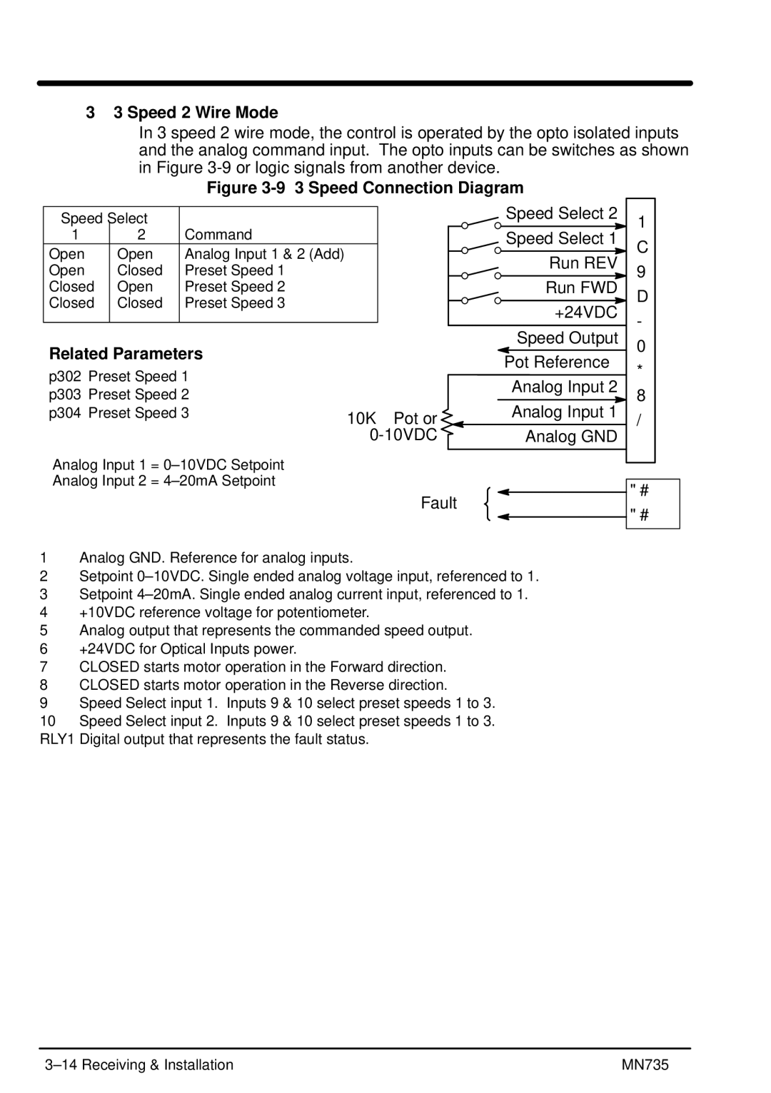
Figure 3-9 3 Speed Connection Diagram
Speed | Select |
|
1 | 2 | Command |
Open | Open | Analog Input 1 & 2 (Add) |
Open | Closed | Preset Speed 1 |
Closed | Open | Preset Speed 2 |
Closed | Closed | Preset Speed 3 |
|
|
|
Related Parameters
Speed Select 2
Speed Select 1
Run REV
Run FWD
+24VDC
Speed Output
Pot Reference
10
9
8
7
6
5
4
p302 Preset Speed 1
p303 Preset Speed 2
p304 Preset Speed 3
10KW Pot or
Analog Input 2
Analog Input 1
Analog GND
3
2
1
Analog Input 1 =
Analog Input 2 =
Fault
RLY1A
RLY1B
1Analog GND. Reference for analog inputs.
2Setpoint
3Setpoint
4+10VDC reference voltage for potentiometer.
5Analog output that represents the commanded speed output.
6+24VDC for Optical Inputs power.
7CLOSED starts motor operation in the Forward direction.
8CLOSED starts motor operation in the Reverse direction.
9Speed Select input 1. Inputs 9 & 10 select preset speeds 1 to 3.
10Speed Select input 2. Inputs 9 & 10 select preset speeds 1 to 3. RLY1 Digital output that represents the fault status.
MN735 |