Section 5.1

ENGINE OIL SYSTEM

The breather serves to maintain a partial vacuum in the engine crankcase, to prevent oil from being forced past oil seals, gaskets or rings.

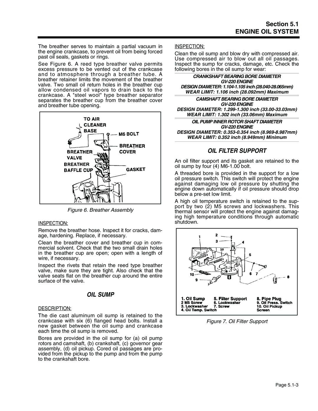
See Figure 6. A reed type breather valve permits excess pressure to be vented out of the crankcase and to atmosphere through a breather tube. A breather retainer limits the movement of the breather valve. Two small oil return holes in the breather cup allow condensed oil vapors to drain back to the crankcase. A "steel wool" type breather separator separates the breather cup from the breather cover and breather tube opening.

Figure 6. Breather Assembly

INSPECTION:

Remove the breather hose. Inspect it for cracks, dam- age, hardening. Replace, if necessary.

Clean the breather cover and breather cup in com- mercial solvent. Check that the two small drain holes in the breather cup are open; open with a length of wire, if necessary.

Inspect the rivets that retain the reed type breather valve, make sure they are tight. Also check that the valve seats flat on the breather cup around the entire surface of the valve.

OIL SUMP

DESCRIPTION:

The die cast aluminum oil sump is retained to the crankcase with six (6) flanged head bolts. Install a new gasket between the oil sump and crankcase each time the oil sump is removed.

Bores are provided in the oil sump for (a) oil pump rotors and camshaft, (b) crankshaft, (c) governor gear assembly, (d) oil pickup. Cored oil passages are pro- vided from the pickup to the pump and from the pump to the crankshaft bore.

INSPECTION:

Clean the oil sump and blow dry with compressed air. Use compressed air to blow out all oil passages. Inspect the sump for cracks, damage, etc. Check the following bores in the oil sump for wear:

CRANKSHAFT BEARING BORE DIAMETER

GV-220 ENGINE

DESIGN DIAMETER: 1.104-1.105 inch (28.040-28.065mm) WEAR LIMIT: 1.106 inch (28.092mm) Maximum

CAMSHAFT BEARING BORE DIAMETER

GV-220 ENGINE

DESIGN DIAMETER: 1.299-1.300 inch (33.00-33.03mm)

WEAR LIMIT: 1.302 inch (33.06mm) Maximum

OIL PUMP INNER ROTOR SHAFT DIAMETER

GV-220 ENGINE

DESIGN DIAMETER: 0.353-0.354 inch (8.969-8.987mm)

WEAR LIMIT: 0.352 inch (8.949mm) Minimum

OIL FILTER SUPPORT

An oil filter support and its gasket are retained to the oil sump by four (4) M6-1.00 bolt.

A threaded bore is provided in the support for a low oil pressure switch. This switch will protect the engine against damaging low oil pressure by shutting the engine down automatically if oil pressure should drop below a pre-set low limit.

A high oil temperature switch is retained to the sup- port by two (2) M5 screws and lockwashers. This thermal sensor will protect the engine against damag- ing high temperature conditions through automatic shutdown.

Figure 7. Oil Filter Support

Page 5.1-3

Page 85
Image 85
Generac Power Systems 941-2, 940-2 service manual OIL Sump, OIL Filter Support

941-2, 940-2 specifications

Generac Power Systems has established a strong reputation in the field of backup power solutions, particularly with its innovative products like the Generac 940-2 and 941-2 generator systems. These generators are designed to provide reliable power during emergencies, ensuring that homes and businesses can maintain operations seamlessly when grid power is disrupted.

One of the standout features of the Generac 940-2 and 941-2 models is their robust engine performance. Both generators utilize Generac’s patented engines, known for their durability and efficiency. These engines are built to withstand the most demanding conditions while providing a consistent power output. This reliability is crucial for users who depend on uninterrupted power supply for essential appliances and equipment.

In terms of technologies, the Generac 940-2 and 941-2 are equipped with advanced automatic transfer switch capabilities. This technology allows the generators to automatically start and supply power within seconds of an outage. This quick response time helps to ensure that critical systems remain operational without noticeable interruptions, which is vital for businesses and households alike.

Another important characteristic of these models is their user-friendly interface. The generators come with an intuitive digital controller that provides real-time information on power usage, system status, and maintenance needs. This technology makes it easy for users to monitor their generators and ensure they are always ready for an emergency.

The design of the Generac 940-2 and 941-2 also emphasizes noise reduction and aesthetic appeal. These units are engineered for quieter operation compared to traditional generators, making them suitable for residential areas. Their sleek appearance also fits well with modern home exteriors, enhancing rather than detracting from the property’s visual appeal.

Furthermore, these generators offer flexible fuel options, with the ability to run on natural gas or propane. This versatility allows users to choose the fuel source that best meets their needs, contributing to energy efficiency and lowering overall operating costs.

In summary, the Generac Power Systems 940-2 and 941-2 are exceptional generators that combine powerful performance with innovative technologies. Their automatic transfer switch capabilities, user-friendly controls, noise reduction features, and flexible fuel options make them an excellent choice for anyone seeking reliable backup power solutions. With these generators, users can rest assured knowing they have a dependable energy source ready when they need it most.