Section 2.3

PISTON, RINGS, CONNECTING ROD

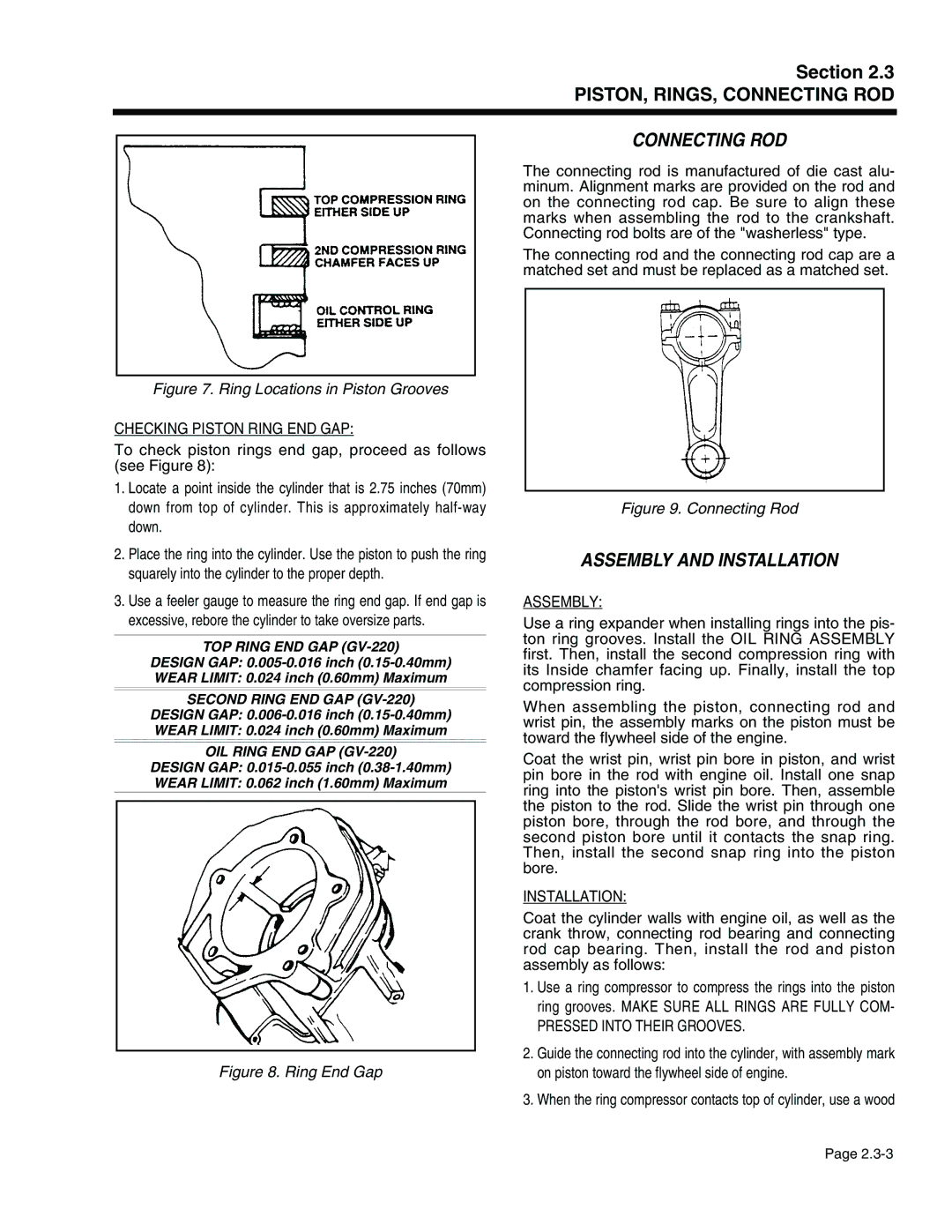
Figure 7. Ring Locations in Piston Grooves

CHECKING PISTON RING END GAP:

To check piston rings end gap, proceed as follows (see Figure 8):

1.Locate a point inside the cylinder that is 2.75 inches (70mm) down from top of cylinder. This is approximately half-way down.

2.Place the ring into the cylinder. Use the piston to push the ring squarely into the cylinder to the proper depth.

3.Use a feeler gauge to measure the ring end gap. If end gap is excessive, rebore the cylinder to take oversize parts.

TOP RING END GAP (GV-220)

DESIGN GAP: 0.005-0.016 inch (0.15-0.40mm) WEAR LIMIT: 0.024 inch (0.60mm) Maximum

SECOND RING END GAP (GV-220)

DESIGN GAP: 0.006-0.016 inch (0.15-0.40mm) WEAR LIMIT: 0.024 inch (0.60mm) Maximum

OIL RING END GAP (GV-220)

DESIGN GAP: 0.015-0.055 inch (0.38-1.40mm) WEAR LIMIT: 0.062 inch (1.60mm) Maximum

Figure 8. Ring End Gap

CONNECTING ROD

The connecting rod is manufactured of die cast alu- minum. Alignment marks are provided on the rod and on the connecting rod cap. Be sure to align these marks when assembling the rod to the crankshaft. Connecting rod bolts are of the "washerless" type.

The connecting rod and the connecting rod cap are a matched set and must be replaced as a matched set.

Figure 9. Connecting Rod

ASSEMBLY AND INSTALLATION

ASSEMBLY:

Use a ring expander when installing rings into the pis- ton ring grooves. Install the OIL RING ASSEMBLY first. Then, install the second compression ring with its Inside chamfer facing up. Finally, install the top compression ring.

When assembling the piston, connecting rod and wrist pin, the assembly marks on the piston must be toward the flywheel side of the engine.

Coat the wrist pin, wrist pin bore in piston, and wrist pin bore in the rod with engine oil. Install one snap ring into the piston's wrist pin bore. Then, assemble the piston to the rod. Slide the wrist pin through one piston bore, through the rod bore, and through the second piston bore until it contacts the snap ring. Then, install the second snap ring into the piston bore.

INSTALLATION:

Coat the cylinder walls with engine oil, as well as the crank throw, connecting rod bearing and connecting rod cap bearing. Then, install the rod and piston assembly as follows:

1.Use a ring compressor to compress the rings into the piston ring grooves. MAKE SURE ALL RINGS ARE FULLY COM-

PRESSED INTO THEIR GROOVES.

2.Guide the connecting rod into the cylinder, with assembly mark on piston toward the flywheel side of engine.

3.When the ring compressor contacts top of cylinder, use a wood

Page 2.3-3

Page 49
Image 49
Generac Power Systems 941-2, 940-2 service manual Connecting ROD, Assembly and Installation

941-2, 940-2 specifications

Generac Power Systems has established a strong reputation in the field of backup power solutions, particularly with its innovative products like the Generac 940-2 and 941-2 generator systems. These generators are designed to provide reliable power during emergencies, ensuring that homes and businesses can maintain operations seamlessly when grid power is disrupted.

One of the standout features of the Generac 940-2 and 941-2 models is their robust engine performance. Both generators utilize Generac’s patented engines, known for their durability and efficiency. These engines are built to withstand the most demanding conditions while providing a consistent power output. This reliability is crucial for users who depend on uninterrupted power supply for essential appliances and equipment.

In terms of technologies, the Generac 940-2 and 941-2 are equipped with advanced automatic transfer switch capabilities. This technology allows the generators to automatically start and supply power within seconds of an outage. This quick response time helps to ensure that critical systems remain operational without noticeable interruptions, which is vital for businesses and households alike.

Another important characteristic of these models is their user-friendly interface. The generators come with an intuitive digital controller that provides real-time information on power usage, system status, and maintenance needs. This technology makes it easy for users to monitor their generators and ensure they are always ready for an emergency.

The design of the Generac 940-2 and 941-2 also emphasizes noise reduction and aesthetic appeal. These units are engineered for quieter operation compared to traditional generators, making them suitable for residential areas. Their sleek appearance also fits well with modern home exteriors, enhancing rather than detracting from the property’s visual appeal.

Furthermore, these generators offer flexible fuel options, with the ability to run on natural gas or propane. This versatility allows users to choose the fuel source that best meets their needs, contributing to energy efficiency and lowering overall operating costs.

In summary, the Generac Power Systems 940-2 and 941-2 are exceptional generators that combine powerful performance with innovative technologies. Their automatic transfer switch capabilities, user-friendly controls, noise reduction features, and flexible fuel options make them an excellent choice for anyone seeking reliable backup power solutions. With these generators, users can rest assured knowing they have a dependable energy source ready when they need it most.