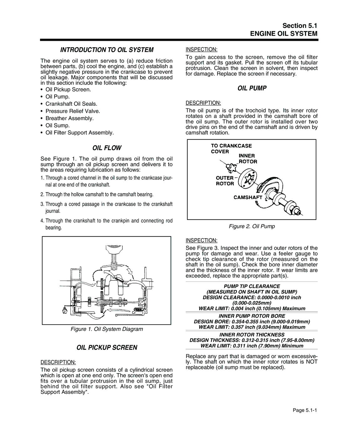
941-2, 940-2 specifications
Generac Power Systems has established a strong reputation in the field of backup power solutions, particularly with its innovative products like the Generac 940-2 and 941-2 generator systems. These generators are designed to provide reliable power during emergencies, ensuring that homes and businesses can maintain operations seamlessly when grid power is disrupted.One of the standout features of the Generac 940-2 and 941-2 models is their robust engine performance. Both generators utilize Generac’s patented engines, known for their durability and efficiency. These engines are built to withstand the most demanding conditions while providing a consistent power output. This reliability is crucial for users who depend on uninterrupted power supply for essential appliances and equipment.
In terms of technologies, the Generac 940-2 and 941-2 are equipped with advanced automatic transfer switch capabilities. This technology allows the generators to automatically start and supply power within seconds of an outage. This quick response time helps to ensure that critical systems remain operational without noticeable interruptions, which is vital for businesses and households alike.
Another important characteristic of these models is their user-friendly interface. The generators come with an intuitive digital controller that provides real-time information on power usage, system status, and maintenance needs. This technology makes it easy for users to monitor their generators and ensure they are always ready for an emergency.
The design of the Generac 940-2 and 941-2 also emphasizes noise reduction and aesthetic appeal. These units are engineered for quieter operation compared to traditional generators, making them suitable for residential areas. Their sleek appearance also fits well with modern home exteriors, enhancing rather than detracting from the property’s visual appeal.
Furthermore, these generators offer flexible fuel options, with the ability to run on natural gas or propane. This versatility allows users to choose the fuel source that best meets their needs, contributing to energy efficiency and lowering overall operating costs.
In summary, the Generac Power Systems 940-2 and 941-2 are exceptional generators that combine powerful performance with innovative technologies. Their automatic transfer switch capabilities, user-friendly controls, noise reduction features, and flexible fuel options make them an excellent choice for anyone seeking reliable backup power solutions. With these generators, users can rest assured knowing they have a dependable energy source ready when they need it most.

