Section 3.4

CARBURETOR

ADJUSTMENT

The carburetor used on the GV-220 engine has a FIXED, NON-ADJUSTABLE Low Speed Jet.

ENGINE SPEED

Engine speed is controlled by the A6060 circuit board. That circuit board signals a stepper motor which moves the throttle linkage. Engine speed will vary in response to changes in generator AC output voltage.

The circuit board monitors the demand for power and adjusts the engine speed accordingly. This permits the engine to deliver only the power needed.

NOTE: Do NOT attempt to accelerate the engine manually by, grasping the throttle or throttle link- age. This win cause the system to enter a fault condition and terminate generator AC output.

THROTTLE LINKAGE ADJUSTMENT

If necessary, the length of the linkage between the stepper motor and the carburetor throttle lever arm can be adjusted. This adjustment helps to establish the proper travel relationship of the linkage. If the adjustment is not correct, the A6060 board will not be able to control the full range of engine speed. The fol- lowing conditions might occur:

If the throttle linkage is set too short, the system will not be able to provide wide open throttle or full power conditions.

If the linkage is set too long, the system will not be able to provide closed throttle or no power condi- tions.

Use the following procedure to ensure the linkage rod is properly adjusted:

1.Start the engine and immediately shut it down. As the engine coasts to a stop, observe from above the engine as the carbu- retor throttle lever rotates counterclockwise.

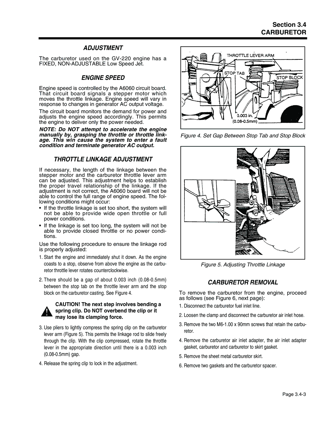
2.There should be a gap of about 0.003 inch (0.08-0.5mm) between the stop tab on the throttle lever arm and the stop block on the carburetor casting. See Figure 4.

CAUTION! The next step involves bending a

!spring clip. Do NOT overbend the clip or it may lose its clamping force.

3.Use pliers to lightly compress the spring clip on the carburetor lever arm (Figure 5). This permits the linkage rod to slide freely through the clip. With the clip compressed, rotate the throttle lever in the appropriate direction until there is a 0.003 inch (0.08-0.5mm) gap.

4.Release the spring clip to lock in the adjustment.

Figure 4. Set Gap Between Stop Tab and Stop Block

Figure 5. Adjusting Throttle Linkage

CARBURETOR REMOVAL

To remove the carburetor from the engine, proceed as follows (see Figure 6, next page):

1.Disconnect the carburetor fuel inlet line.

2.Loosen the clamp and disconnect the carburetor air inlet hose.

3.Remove the two M6-1.00 x 90mm screws that retain the carbu- retor.

4.Remove the carburetor air inlet adapter, the air inlet adapter gasket, carburetor and carburetor to skirt gasket.

5.Remove the sheet metal carburetor skirt.

6.Remove two gaskets and the carburetor spacer.

Page 3.4-3

Page 65
Image 65
Generac Power Systems 941-2, 940-2 service manual Engine Speed, Throttle Linkage Adjustment, Carburetor Removal

941-2, 940-2 specifications

Generac Power Systems has established a strong reputation in the field of backup power solutions, particularly with its innovative products like the Generac 940-2 and 941-2 generator systems. These generators are designed to provide reliable power during emergencies, ensuring that homes and businesses can maintain operations seamlessly when grid power is disrupted.

One of the standout features of the Generac 940-2 and 941-2 models is their robust engine performance. Both generators utilize Generac’s patented engines, known for their durability and efficiency. These engines are built to withstand the most demanding conditions while providing a consistent power output. This reliability is crucial for users who depend on uninterrupted power supply for essential appliances and equipment.

In terms of technologies, the Generac 940-2 and 941-2 are equipped with advanced automatic transfer switch capabilities. This technology allows the generators to automatically start and supply power within seconds of an outage. This quick response time helps to ensure that critical systems remain operational without noticeable interruptions, which is vital for businesses and households alike.

Another important characteristic of these models is their user-friendly interface. The generators come with an intuitive digital controller that provides real-time information on power usage, system status, and maintenance needs. This technology makes it easy for users to monitor their generators and ensure they are always ready for an emergency.

The design of the Generac 940-2 and 941-2 also emphasizes noise reduction and aesthetic appeal. These units are engineered for quieter operation compared to traditional generators, making them suitable for residential areas. Their sleek appearance also fits well with modern home exteriors, enhancing rather than detracting from the property’s visual appeal.

Furthermore, these generators offer flexible fuel options, with the ability to run on natural gas or propane. This versatility allows users to choose the fuel source that best meets their needs, contributing to energy efficiency and lowering overall operating costs.

In summary, the Generac Power Systems 940-2 and 941-2 are exceptional generators that combine powerful performance with innovative technologies. Their automatic transfer switch capabilities, user-friendly controls, noise reduction features, and flexible fuel options make them an excellent choice for anyone seeking reliable backup power solutions. With these generators, users can rest assured knowing they have a dependable energy source ready when they need it most.