5
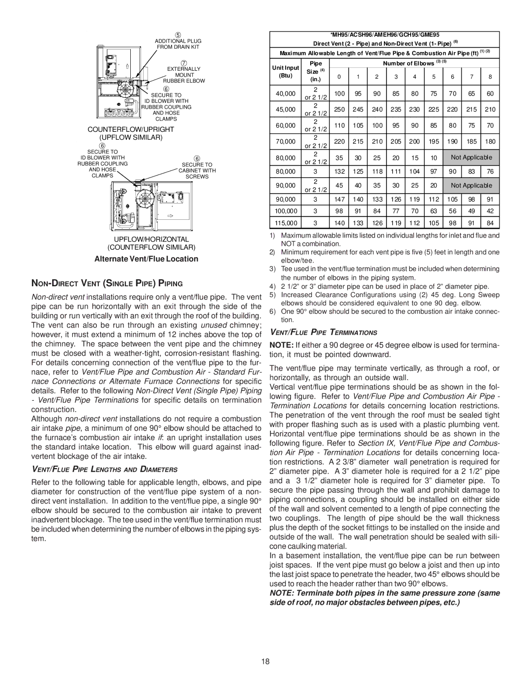
ADDITIONAL PLUG FROM DRAIN KIT
7 |
EXTERNALLY |
MOUNT |
RUBBER ELBOW |
6 |
SECURE TO |
ID BLOWER WITH |
RUBBER COUPLING |
AND HOSE |
CLAMPS |
COUNTERFLOW/UPRIGHT |
(UPFLOW SIMILAR) |
6 |
|
SECURE TO |
|
ID BLOWER WITH | 6 |
RUBBER COUPLING | SECURE TO |
AND HOSE | CABINET WITH |
CLAMPS | SCREWS |
UPFLOW/HORIZONTAL
(COUNTERFLOW SIMILAR)
Alternate Vent/Flue Location
NON-DIRECT VENT (SINGLE PIPE) PIPING
-Vent/Flue Pipe Terminations for specific details on termination construction.
Although
VENT/FLUE PIPE LENGTHS AND DIAMETERS
Refer to the following table for applicable length, elbows, and pipe diameter for construction of the vent/flue pipe system of a non- direct vent installation. In addition to the vent/flue pipe, a single 90° elbow should be secured to the combustion air intake to prevent inadvertent blockage. The tee used in the vent/flue termination must be included when determining the number of elbows in the piping sys- tem.
*MH95/ACSH96/AMEH96/GCH95/GME95 Direct Vent (2 - Pipe) and
Maximum Allowable Length of Vent/Flue Pipe & Combustion Air Pipe (ft) (1) (2)
Unit Input | Pipe |
|
|
| Number of Elbows (3) (5) |
|
|
| ||||
Size (4) | 0 | 1 | 2 |
| 3 | 4 | 5 |
| 6 | 7 | 8 | |
(Btu) | (in.) |
|
| |||||||||
|
|
|
|
|
|
|
|
|
|
|
| |
|
|
|
|
|
|
|
|
|
|
|
|
|
40,000 | 2 | 100 | 95 | 90 |
| 85 | 80 | 75 |
| 70 | 65 | 60 |
or 2 1/2 |
|
| ||||||||||
|
|
|
|
|
|
|
|
|
|
|
| |
45,000 | 2 | 250 | 245 | 240 |
| 235 | 230 | 225 |
| 220 | 215 | 210 |
or 2 1/2 |
|
| ||||||||||
|
|
|
|
|
|
|
|
|
|
|
| |
60,000 | 2 | 110 | 105 | 100 |
| 95 | 90 | 85 |
| 80 | 75 | 70 |
or 2 1/2 |
|
| ||||||||||
|
|
|
|
|
|
|
|
|
|
|
| |
70,000 | 2 | 220 | 215 | 210 |
| 205 | 200 | 195 |
| 190 | 185 | 180 |
or 2 1/2 |
|
| ||||||||||
|
|
|
|
|
|
|
|
|
|
|
| |
80,000 | 2 | 35 | 30 | 25 |
| 20 | 15 | 10 |
| Not Applicable | ||
or 2 1/2 |
|
| ||||||||||
|
|
|
|
|
|
|
|
|
|
|
| |
80,000 | 3 | 132 | 125 | 118 |
| 111 | 104 | 97 |
| 90 | 83 | 76 |
|
|
|
|
|
|
|
|
|
|
|
|
|
90,000 | 2 | 45 | 40 | 35 |
| 30 | 25 | 20 |
| Not Applicable | ||
or 2 1/2 |
|
| ||||||||||
|
|
|
|
|
|
|
|
|
|
|
| |
90,000 | 3 | 147 | 140 | 133 |
| 126 | 119 | 112 |
| 105 | 98 | 91 |
|
|
|
|
|
|
|
|
|
|
|
|
|
100,000 | 3 | 98 | 91 | 84 |
| 77 | 70 | 63 |
| 56 | 49 | 42 |
115,000 | 3 | 140 | 133 | 126 |
| 119 | 112 | 105 |
| 98 | 91 | 84 |
1)Maximum allowable limits listed on individual lengths for inlet and flue and NOT a combination.
2)Minimum requirement for each vent pipe is five (5) feet in length and one elbow/tee.
3)Tee used in the vent/flue termination must be included when determining the number of elbows in the piping system.
4)2 1/2” or 3” diameter pipe can be used in place of 2” diameter pipe.
5)Increased Clearance Configurations using (2) 45 deg. Long Sweep elbows should be considered equivalent to one 90 deg. elbow.
6)One 90° elbow should be secured to the combustion air intake connec- tion.
VENT/FLUE PIPE TERMINATIONS
NOTE: If either a 90 degree or 45 degree elbow is used for termina- tion, it must be pointed downward.
The vent/flue pipe may terminate vertically, as through a roof, or horizontally, as through an outside wall.
Vertical vent/flue pipe terminations should be as shown in the fol- lowing figure. Refer to Vent/Flue Pipe and Combustion Air Pipe - Termination Locations for details concerning location restrictions. The penetration of the vent through the roof must be sealed tight with proper flashing such as is used with a plastic plumbing vent. Horizontal vent/flue pipe terminations should be as shown in the following figure. Refer to Section IX, Vent/Flue Pipe and Combus- tion Air Pipe - Termination Locations for details concerning loca- tion restrictions. A 2 3/8” diameter wall penetration is required for 2” diameter pipe. A 3” diameter hole is required for a 2 1/2” pipe and a 3 1/2” diameter hole is required for 3” diameter pipe. To secure the pipe passing through the wall and prohibit damage to piping connections, a coupling should be installed on either side of the wall and solvent cemented to a length of pipe connecting the two couplings. The length of pipe should be the wall thickness plus the depth of the socket fittings to be installed on the inside and outside of the wall. The wall penetration should be sealed with sili- cone caulking material.
In a basement installation, the vent/flue pipe can be run between joist spaces. If the vent pipe must go below a joist and then up into the last joist space to penetrate the header, two 45° elbows should be used to reach the header rather than two 90° elbows.
NOTE: Terminate both pipes in the same pressure zone (same side of roof, no major obstacles between pipes, etc.)
18