Natural Gas Capacity of Pipe
In Cubic Feet of Gas Per Hour (CFH)
Length of |
| Nominal Black Pipe Size |
| ||
Pipe in Feet | 1/2" | 3/4" | 1" | 1 1/4" | 1 1/2" |
10 | 132 | 278 | 520 | 1050 | 1600 |
20 | 92 | 190 | 350 | 730 | 1100 |
30 | 73 | 152 | 285 | 590 | 980 |
40 | 63 | 130 | 245 | 500 | 760 |
50 | 56 | 115 | 215 | 440 | 670 |
60 | 50 | 105 | 195 | 400 | 610 |
70 | 46 | 96 | 180 | 370 | 560 |
80 | 43 | 90 | 170 | 350 | 530 |
90 | 40 | 84 | 160 | 320 | 490 |
100 | 38 | 79 | 150 | 305 | 460 |
(Pressure 0.5 psig or less and pressure drop of 0.3" W.C.; Based on
rigid pipe must be used to reach the outside of the cabinet. A
•Use listed gas appliance connectors in accordance with their instructions. Connectors must be fully in the same room as the furnace.
•Protect connectors and
0.60 Specific Gravity Gas)
CFH = BTUH Furnace Input
Heating Value of Gas (BTU/Cubic Foot)
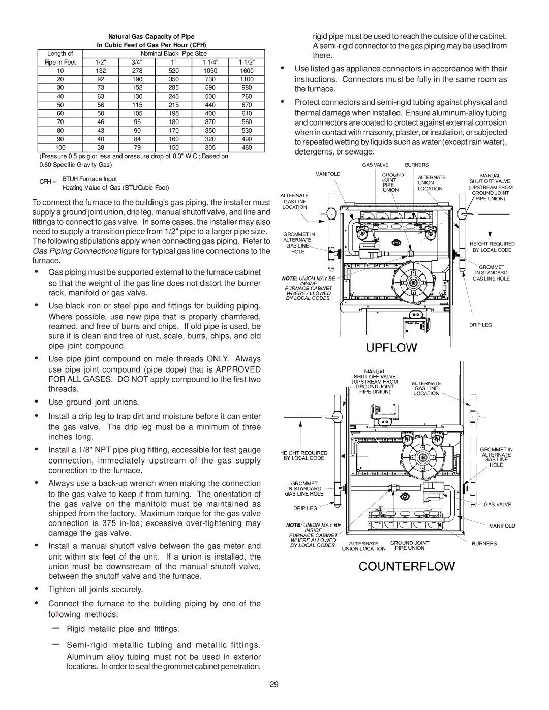
To connect the furnace to the building’s gas piping, the installer must supply a ground joint union, drip leg, manual shutoff valve, and line and fittings to connect to gas valve. In some cases, the installer may also need to supply a transition piece from 1/2" pipe to a larger pipe size. The following stipulations apply when connecting gas piping. Refer to Gas Piping Connections figure for typical gas line connections to the furnace.
• Gas piping must be supported external to the furnace cabinet |
so that the weight of the gas line does not distort the burner |
rack, manifold or gas valve. |
• Use black iron or steel pipe and fittings for building piping. |
Where possible, use new pipe that is properly chamfered, |
reamed, and free of burrs and chips. If old pipe is used, be |
sure it is clean and free of rust, scale, burrs, chips, and old |
pipe joint compound. |
• Use pipe joint compound on male threads ONLY. Always |
use pipe joint compound (pipe dope) that is APPROVED |
FOR ALL GASES. DO NOT apply compound to the first two |
GAS VALVE | BURNERS | |
MANIFOLD | ALTERNATE | |
| ||
PIPE | UNION | |
LOCATION | ||
UNION | ||
GAS LINE |
| |
GROMMET IN |
| |
GAS LINE |
| |
HOLE |
|
MANUAL
SHUT OFF VALVE (UPSTREAM FROM
PIPE UNION)
HEIGHT REQUIRED
BY LOCAL CODE
GROMMET
IN STANDARD
GAS LINE HOLE
DRIP LEG
threads. |
• Use ground joint unions. |
• Install a drip leg to trap dirt and moisture before it can enter |
the gas valve. The drip leg must be a minimum of three |
inches long. |
• Install a 1/8" NPT pipe plug fitting, accessible for test gauge |
connection, immediately upstream of the gas supply |
connection to the furnace. |
• Always use a |
to the gas valve to keep it from turning. The orientation of |
the gas valve on the manifold must be maintained as |
shipped from the factory. Maximum torque for the gas valve |
connection is 375 |
damage the gas valve. |
• Install a manual shutoff valve between the gas meter and |
unit within six feet of the unit. If a union is installed, the |
union must be downstream of the manual shutoff valve, |
between the shutoff valve and the furnace. |
• Tighten all joints securely. |
• Connect the furnace to the building piping by one of the |
following methods: |
– Rigid metallic pipe and fittings. |
– |
Aluminum alloy tubing must not be used in exterior |
locations. In order to seal the grommet cabinet penetration, |
| GROMMET IN |
| ALTERNATE |
| GAS LINE |
| HOLE |
DRIP LEG | GAS VALVE |
| |
| BURNERS |
29