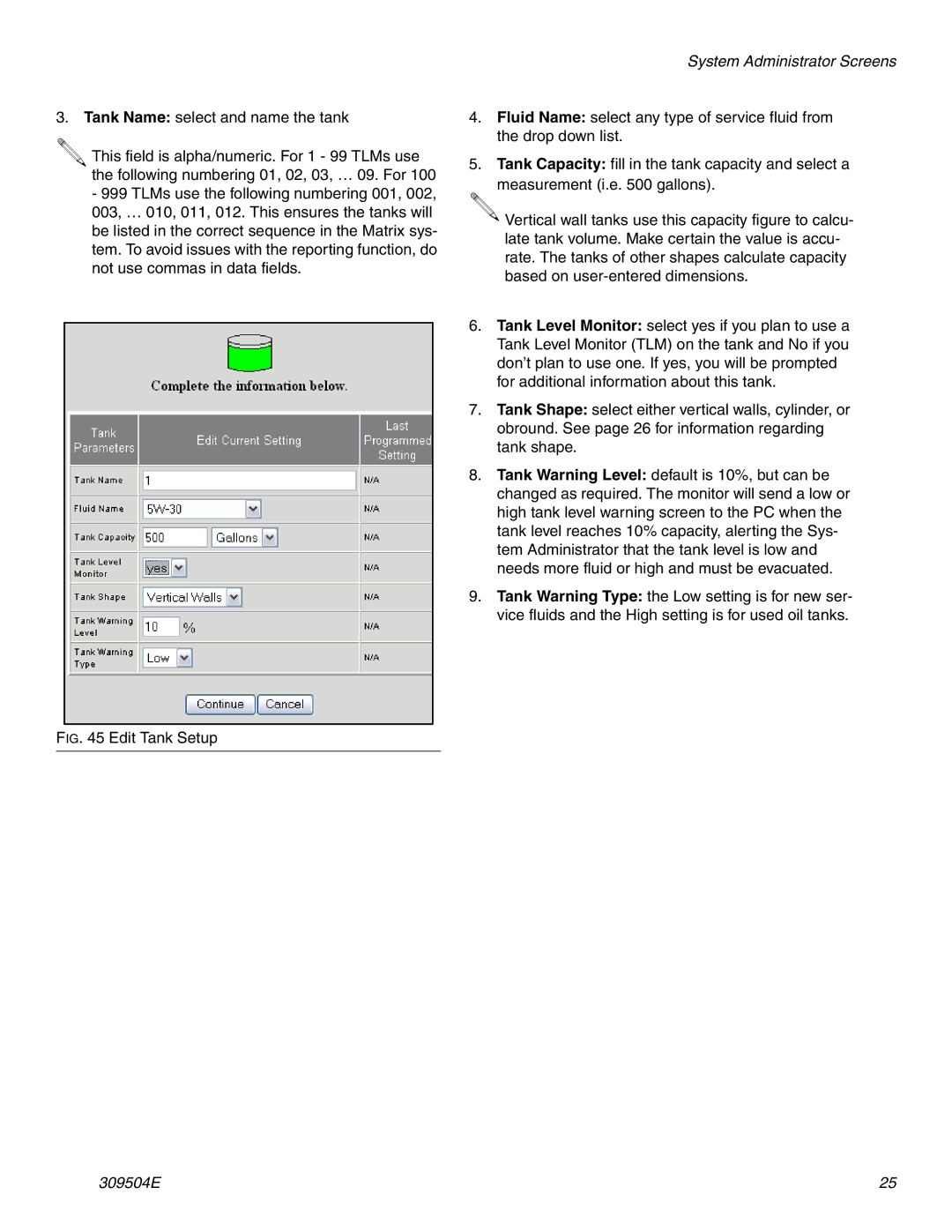
3. Tank Name: select and name the tank
.![]()
![]()
This field is alpha/numeric. For 1 - 99 TLMs use the following numbering 01, 02, 03, … 09. For 100
-999 TLMs use the following numbering 001, 002, 003, … 010, 011, 012. This ensures the tanks will be listed in the correct sequence in the Matrix sys- tem. To avoid issues with the reporting function, do not use commas in data fields.
System Administrator Screens
4.Fluid Name: select any type of service fluid from the drop down list.
5.Tank Capacity: fill in the tank capacity and select a measurement (i.e. 500 gallons).
![]() Vertical wall tanks use this capacity figure to calcu- late tank volume. Make certain the value is accu- rate. The tanks of other shapes calculate capacity based on
Vertical wall tanks use this capacity figure to calcu- late tank volume. Make certain the value is accu- rate. The tanks of other shapes calculate capacity based on
6.Tank Level Monitor: select yes if you plan to use a Tank Level Monitor (TLM) on the tank and No if you don’t plan to use one. If yes, you will be prompted for additional information about this tank.
7.Tank Shape: select either vertical walls, cylinder, or obround. See page 26 for information regarding tank shape.
8.Tank Warning Level: default is 10%, but can be changed as required. The monitor will send a low or high tank level warning screen to the PC when the tank level reaches 10% capacity, alerting the Sys- tem Administrator that the tank level is low and needs more fluid or high and must be evacuated.
9.Tank Warning Type: the Low setting is for new ser- vice fluids and the High setting is for used oil tanks.
FIG. 45 Edit Tank Setup
309504E | 25 |
