Ground System
•Reactor: is grounded through power cord; see page 15.
•Spray gun: connect whip hose ground wire to FTS; see page 18. Do not disconnect wire or spray with- out whip hose.
•Fluid supply containers: follow your local code.
•Object being sprayed: follow your local code.
•Solvent pails used when flushing: follow your local code. Use only metal pails that are conductive. Place them on a grounded surface. Do no place pail on a nonconductive surface, such as paper or cardboard, which interrupts grounding continuity.
•To maintain grounding continuity when flushing or relieving pressure, hold a metal part of spray gun firmly to the side of a grounded metal pail, then trigger gun.
Iso Pump Lubrication System Setup
Prepare isocyanate pump lubrication system as follows:
1.Lift lubricant reservoir out of bracket and remove reservoir from cap.
2.Fill reservoir 3/4 full with TSL; see Accessories section in manual 311512.
3.Thread reservoir onto cap assembly and place it into bracket.
The lubrication system is now ready for operation; no priming is required.
Fluid Supply Connections
Connect material supply to inlets of proportioning unit as follows:
1.Ensure the A- and B- inlet ball valves (U,X) on proportioning unit are closed.
Setup
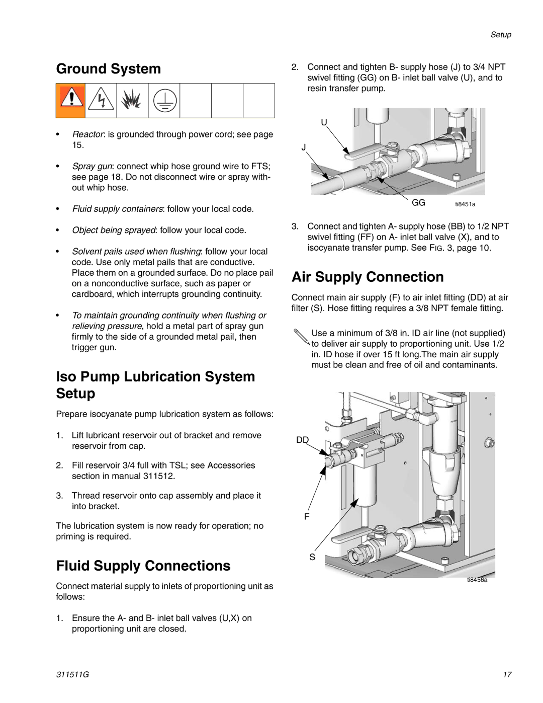
2.Connect and tighten B- supply hose (J) to 3/4 NPT swivel fitting (GG) on B- inlet ball valve (U), and to resin transfer pump.
U
J
GG ti8451a
3.Connect and tighten A- supply hose (BB) to 1/2 NPT swivel fitting (FF) on A- inlet ball valve (X), and to isocyanate transfer pump. See FIG. 3, page 10.
Air Supply Connection
Connect main air supply (F) to air inlet fitting (DD) at air filter (S). Hose fitting requires a 3/8 NPT female fitting.
Use a minimum of 3/8 in. ID air line (not supplied) ![]()
![]() to deliver air supply to proportioning unit. Use 1/2 in. ID hose if over 15 ft long.The main air supply must be clean and free of oil and contaminants.
to deliver air supply to proportioning unit. Use 1/2 in. ID hose if over 15 ft long.The main air supply must be clean and free of oil and contaminants.
DD
F
S
ti8456a
311511G | 17 |