Operation
Operation
Daily Start-up Procedure
The daily ![]()
![]() operation. Assume that all temperature and pressure settings have been previously set, but that the heating system is not up to operating temperature.
operation. Assume that all temperature and pressure settings have been previously set, but that the heating system is not up to operating temperature.
1.Check condition isocyanate lubrication system and service as required. Change pump lubricant when it shows signs of change to a milky color.
2.Ensure supply fluid is at correct temperature as recommended by chemical system supplier. Ensure individual chemicals are correctly agitated within their drums/day tanks, and moisture protection system is properly set for operation. Recirculate heated fluid back to supply drums if necessary; see page 31.
3.Turn on main air supply to transfer pumps.
4.Pressurize transfer pumps and open A- and
5.Open air inlet ball valve.
6.Switch ON main power disconnect switch.
7.Uncoil heated hose.
NOTICE
Uncoil heated hoses before turning on hose heater switch to prevent overheating and hot spots within hose.
8.Check that hose setpoint temperature is correct.
9.Turn hose heat control switch past ON to START. Switch will illuminate.
10.The hose power controller automatically adjusts the hose current to the hose to compensate for hose length and ambient temperature. Wait for actual hose temperature readout to match hose setpoint temperature.
11.Turn on primary heater switch past ON to START. Ensure heater setpoint is correct. Wait for operating temperature to be reached.
To prevent excessive pressure
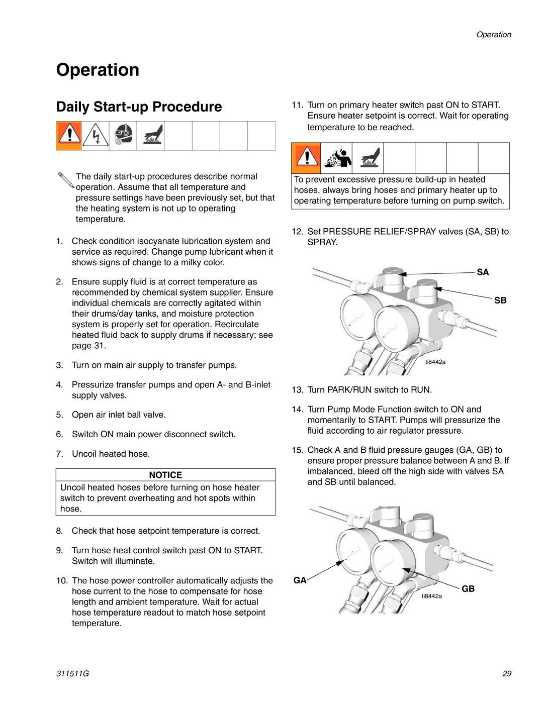
12.Set PRESSURE RELIEF/SPRAY valves (SA, SB) to
SPRAY.
![]() SA
SA
SB
ti8442a
13.Turn PARK/RUN switch to RUN.
14.Turn Pump Mode Function switch to ON and momentarily to START. Pumps will pressurize the fluid according to air regulator pressure.
15.Check A and B fluid pressure gauges (GA, GB) to ensure proper pressure balance between A and B. If imbalanced, bleed off the high side with valves SA and SB until balanced.
GA![]()
GB
ti8442a
311511G | 29 |