Repair
Repair
To avoid serious injury due to the pump assembly falling, secure a hoist to the lift ring.
Follow Shutdown procedure on page 30, which includes flushing, if service time may exceed pot life time, before servicing fluid components, and before transporting system to a service area.
Pump Assembly
The displacement pumps and air motor may be removed and serviced separately or the entire pump and motor assembly can be removed with a hoist.
Remove Pump Assembly
1.Stop the pumps near the bottom of their stroke. Fol- low Shutdown, page 30.
2.Disconnect all hoses from the pump assembly.
3.If hoppers are installed, disconnect the hopper fluid lines from the pump fluid inlet. See Hoppers, page 40.
NOTE: The hopper and hopper bracket do not need to be removed from the cart.
4.Remove screws (6) and washers (5) under the tie plate (101).
5.Use hoist to remove the pump assembly by the lift ring and carefully lift out of cart (1).
Remove Displacement Pump
1.Follow Shutdown, page 30.
2.If hoppers are installed, remove the hopper and hopper bracket from the cart. See Hoppers, page 40.
3.If feed pumps are installed, close the inlet ball valve. Remove inlet union (61).
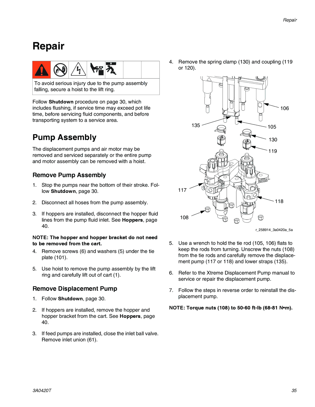
4.Remove the spring clamp (130) and coupling (119 or 120).
106
135 | 105 |
| |
| 130 |
| 119 |
117
![]() 118
118
108
r_258914_3a0420a_5a
5.Use a wrench to hold the tie rod (105, 106) flats to keep the rods from turning. Unscrew the nuts (108) from the tie rods and carefully remove the displace- ment pump (117 or 118) and lower straps (135).
6.Refer to the Xtreme Displacement Pump manual to service or repair the displacement pump.
7.Follow the steps in reverse order to reinstall the dis- placement pump.
NOTE: Torque nuts (108) to
3A0420T | 35 |