Schematic Diagrams

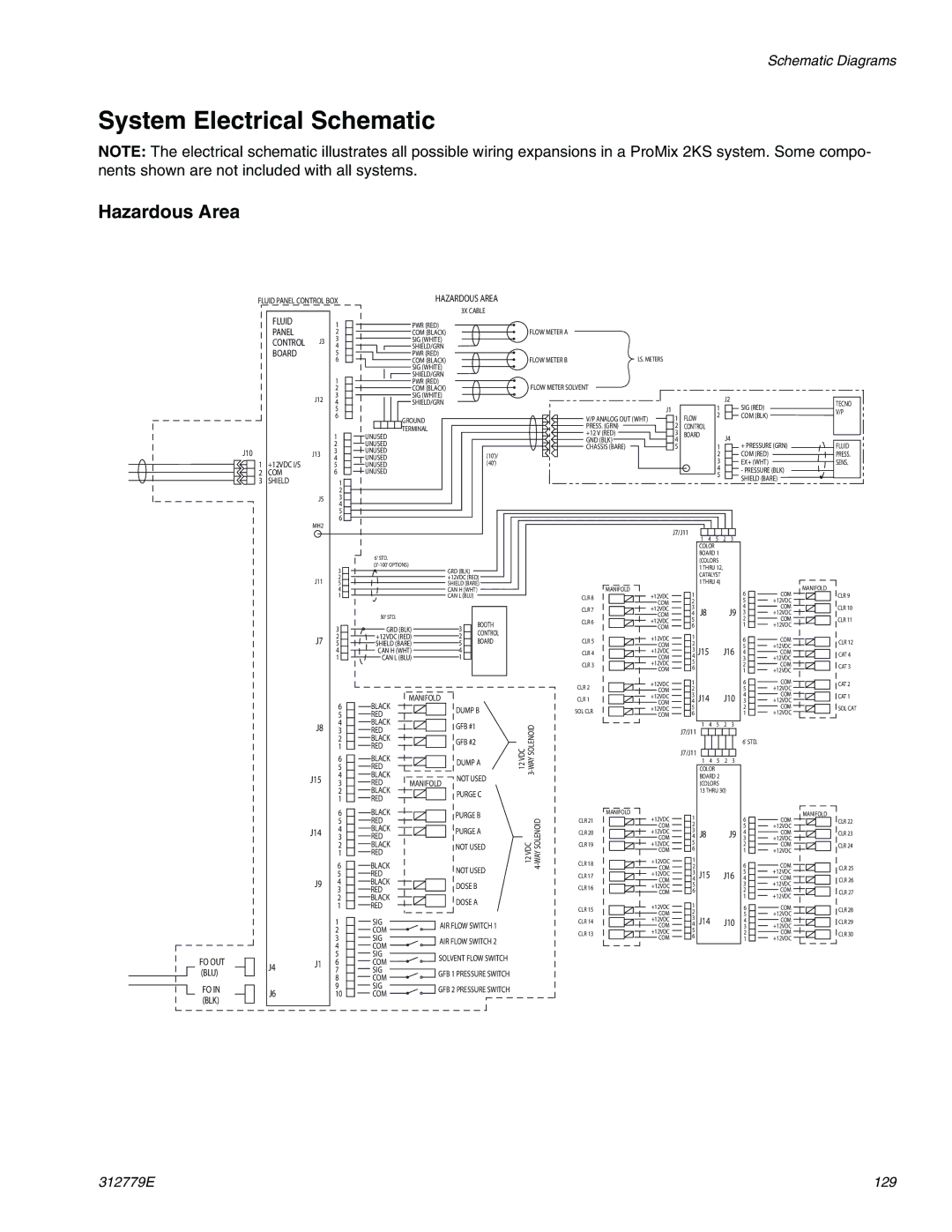
System Electrical Schematic

NOTE: The electrical schematic illustrates all possible wiring expansions in a ProMix 2KS system. Some compo- nents shown are not included with all systems.

Hazardous Area

FLUID PANEL CONTROL BOX


FLUID

1


PANEL

2


CONTROL J3

3


4


BOARD

5


6


1


2


J12

3


4


5


6


1


2

J10

J13

3


1

+12VDC I/S

4


5


2

COM

6


3

SHIELD

1


2


J5

3


4


5


6

MH2

HAZARDOUS AREA

3X CABLE


PWR (RED)


COM (BLACK)


SIG (WHITE)


SHIELD/GRN


PWR (RED)


COM (BLACK)


SIG (WHITE)


SHIELD/GRN


PWR (RED)


COM (BLACK)


SIG (WHITE)


SHIELD/GRN


GROUND


UNUSED


TERMINAL


UNUSED


UNUSED


(10')/


UNUSED


UNUSED


(40')


UNUSED


FLOW METER A


FLOW METER B

I.S. METERS


FLOW METER SOLVENT


1

J2

SIG (RED)

TECNO


J1


V/P


V/P ANALOG OUT (WHT)

1

FLOW


2


COM (BLK)


PRESS. (GRN)

2

CONTROL


+12 V (RED)

3

BOARD


J4


GND (BLK)

4


1

+ PRESSURE (GRN)

FLUID


CHASSIS (BARE)

5


2


COM (RED)

PRESS.


3


EX+ (WHT)

SENS.


4


- PRESSURE (BLK)


5


SHIELD (BARE)


J7/J11

4

5

2

3


1


COLOR


BOARD 1


J11

J7


6' STD.


3

(3'-100' OPTIONS)

GRD (BLK)


2


+12VDC (RED)

5


SHIELD (BARE)

4


CAN H (WHT)


1


CAN L (BLU)


50' STD.


BOOTH

3

GRD (BLK)

3

CONTROL

2

+12VDC (RED)

2

BOARD

5

SHIELD (BARE)

5

4

CAN H (WHT)

4


1

CAN L (BLU)

1


(COLORS


1 THRU 12,


CATALYST


MANIFOLD


1 THRU 4)


MANIFOLD


1


6


COM

CLR 8


+12VDC


5


CLR 9


COM

2


+12VDC


CLR 7


+12VDC

3

J8

J9

4


COM


CLR 10


COM

4

3


+12VDC


CLR 6


+12VDC

5


2


COM


CLR 11


COM

6


1


+12VDC


CLR 5


+12VDC

1


6


COM


CLR 12


COM

2


5


+12VDC


CLR 4


+12VDC

3

J15

J16

4


COM


CAT 4


COM

4


3


+12VDC


CLR 3


+12VDC

5


2


COM


CAT 3


COM


6


1


+12VDC


CLR 2


+12VDC


1


6


COM


CAT 2


COM


2


5


+12VDC


COM


FO OUT (BLU)

FO IN (BLK)

J8

J15

J14

J9

J4 J1

J6

6

5

4

3

2

1

6

5

4

3

2

1

6

5

4

3

2

1

6

5

4

3

2

1

1

2

3

4

5

6

7

8

9

10

BLACK

RED

BLACK

RED

BLACK

RED

BLACK

RED

BLACK

RED

BLACK

RED

BLACK RED BLACK RED BLACK RED

BLACK

RED

BLACK

RED

BLACK

RED

SIG

COM

SIG

COM

SIG

COM

SIG

COM

SIG

COM

MANIFOLD

DUMP B

GFB #1

GFB #2

DUMP A

MANIFOLD NOT USED PURGE C

PURGE B

PURGE A

NOT USED

NOT USED

DOSE B

DOSE A

AIR FLOW SWITCH 1

AIR FLOW SWITCH 2

SOLVENT FLOW SWITCH

GFB 1 PRESSURE SWITCH

GFB 2 PRESSURE SWITCH


CLR 1


+12VDC

3

J14


J10

4


+12VDC


CAT 1


COM

4


3


SOL CLR


+12VDC

5


2


COM


SOL CAT


COM

6


1


+12VDC


12 VDC -WAY SOLENOID


J7/J11

1

4

5

2

3


6' STD.


J7/J11


1

4

5

2

3


COLOR


3


BOARD 2


(COLORS


13 THRU 30)


MANIFOLD

1


MANIFOLD


4-WAY SOLENOID

CLR 21


+12VDC


6


COM


CLR 22


COM

2


5


+12VDC


CLR 20


+12VDC

3

J8


J9

4


COM


CLR 23


COM

4


3


+12VDC


12 VDC

CLR 19


+12VDC

5


2


COM


CLR 24


COM

6


1


+12VDC


CLR 18


+12VDC

1


6


COM


COM

2


CLR 25


CLR 17


+12VDC

3

J15


J16

5


+12VDC


COM

4


4


COM


CLR 26


CLR 16


+12VDC

5


3


+12VDC


2


COM


COM

6


CLR 27


+12VDC

1


1


+12VDC


CLR 15


6


COM


CLR 28


COM


2


5


+12VDC


CLR 14


+12VDC


3

J14


J10

4


COM


CLR 29


COM


4


3


+12VDC


CLR 13


+12VDC


5


2


COM


CLR 30


6


COM


1


+12VDC


312779E

129

Page 129
Image 129
Graco TI12553a, TI12552a important safety instructions Hazardous Area

TI12553a, TI12552a specifications

The Graco TI12552A and TI12553A are highly regarded models in the realm of airless paint sprayers, designed to cater to both professional contractors and DIY enthusiasts. These sprayers are engineered for efficiency and versatility, making them ideal for a variety of painting tasks, including interior and exterior applications.

One of the standout features of the Graco TI12552A and TI12553A is their powerful motor, which delivers consistent pressure for a flawless finish. The motor is backed by a robust design, ensuring durability even during extensive use. This enables users to spray unthinned coatings, making the models suitable for a range of materials, including latex, stains, and sealers.

Both models boast Graco's innovative ProConnect technology, allowing for quick and easy pump replacements. This feature significantly reduces downtime and enhances productivity, as users can replace the pump on-site without needing specialized tools. The Graco TI12552A and TI12553A also feature a lightweight and portable design, making them easy to transport around job sites.

The ergonomics of these sprayers are commendable, with comfortable grips and well-placed controls, allowing for extended use without discomfort. Additionally, the integrated storage compartments enable users to keep accessories like sprayer tips and hoses organized and easily accessible.

Another significant characteristic of the TI12552A and TI12553A is their adjustable pressure control. This allows users to tailor the paint flow to suit specific projects, providing greater control over the application and ensuring optimal results. The models also feature a reversible spray tip, which is a convenient addition that allows for easy unclogging, minimizing interruptions during work.

For safety and maintenance, both models come equipped with a built-in suction filter that prevents debris from entering the system and damaging the pump. Regular maintenance is simplified by the easy-access fluid intake, which allows for straightforward cleaning.

In summary, the Graco TI12552A and TI12553A are advanced airless paint sprayers that combine power, convenience, and versatility. With their user-friendly features, ergonomic design, and innovative technologies, these sprayers are essential tools for anyone looking to achieve professional-quality finishes with ease. Whether it’s a residential project or larger-scale commercial job, the TI12552A and TI12553A stand out as reliable choices in the competitive landscape of paint sprayers.