Repair
Replace Trigger Valve O-Rings
1.Clean gun according to Clean Spray Gun Procedure, page 20.
2.Disconnect air supply from gun.
Refer to Parts, page 30.
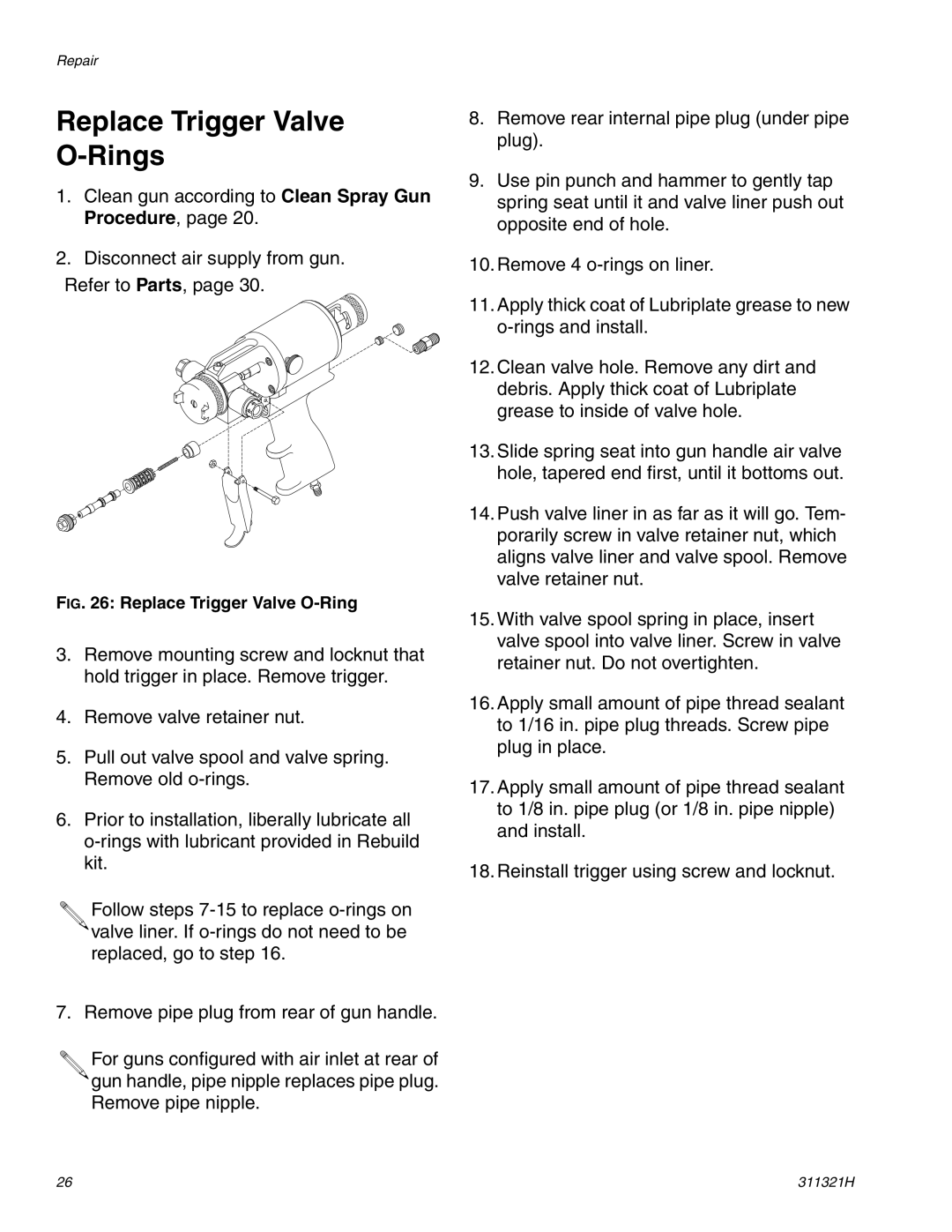
FIG. 26: Replace Trigger Valve O-Ring
3.Remove mounting screw and locknut that hold trigger in place. Remove trigger.
4.Remove valve retainer nut.
5.Pull out valve spool and valve spring. Remove old
6.Prior to installation, liberally lubricate all
![]()
![]() Follow steps
Follow steps
![]() valve liner. If
valve liner. If
7. Remove pipe plug from rear of gun handle.
![]()
![]() For guns configured with air inlet at rear of
For guns configured with air inlet at rear of ![]() gun handle, pipe nipple replaces pipe plug. Remove pipe nipple.
gun handle, pipe nipple replaces pipe plug. Remove pipe nipple.
8.Remove rear internal pipe plug (under pipe plug).
9.Use pin punch and hammer to gently tap spring seat until it and valve liner push out opposite end of hole.
10.Remove 4
11.Apply thick coat of Lubriplate grease to new
12.Clean valve hole. Remove any dirt and debris. Apply thick coat of Lubriplate grease to inside of valve hole.
13.Slide spring seat into gun handle air valve hole, tapered end first, until it bottoms out.
14.Push valve liner in as far as it will go. Tem- porarily screw in valve retainer nut, which aligns valve liner and valve spool. Remove valve retainer nut.
15.With valve spool spring in place, insert valve spool into valve liner. Screw in valve retainer nut. Do not overtighten.
16.Apply small amount of pipe thread sealant to 1/16 in. pipe plug threads. Screw pipe plug in place.
17.Apply small amount of pipe thread sealant to 1/8 in. pipe plug (or 1/8 in. pipe nipple) and install.
18.Reinstall trigger using screw and locknut.
26 | 311321H |