Manuals
/
Graco Inc
/
Power Tools
/
Paint Sprayer
Graco Inc
GX-7 DI, 311321H, GX-7A
important safety instructions
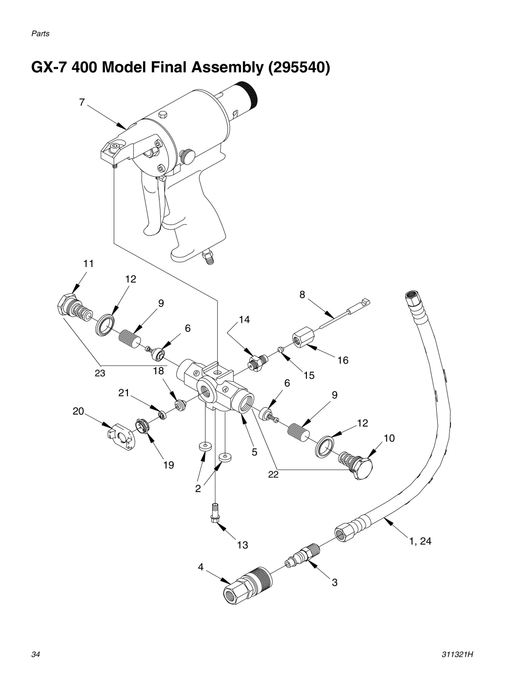
GX-7 400 Model Final Assembly
Models:
GX-7A
311321H
GX-7 DI
GX-7 400
1
34
50
50
Download
50 pages
51.4 Kb
31
32
33
34
35
36
37
38
Specs
Install
Set-Up Chart for GX-7A Model
Warranty
Maintenance
Optional Configuration
Initial Set Up
GX-7A Model Final Assembly
Pressure Relief Procedure
Valving Rod Adjustment
Page 34
Image 34
Parts
GX-7
400 Model Final Assembly (295540)
7
11
12
8
9
14
6
16
23
18
15
21
6
9
20
12
10
5
19
22
2
13
1, 24
4
3
34
311321H
Page 33
Page 35
Page 34
Image 34
Page 33
Page 35
Contents
311321H
Important Safety Instructions
GX-7
Contents
Models
Personal Protective Equipment
Fire and Explosion Hazard
Pressurized Aluminum Parts Hazard
Model GX-7A
Overall View
Model GX-7 DI
Valving Rod Rear Stop Gun Block Air Cap Valve
Model GX-7
Locknut
Trigger
Centerline Components
GX-7A Centerline Components
GX-7 400 Centerline Components
Mixing Module
GX-7A Mixing Module
Isocyanate Hazard
Safety Position
Operation Basics
Keep a and B Components Separate
Connect Air Hoses
Disengage Safety Stop
Air Hose Connection
Disconnect Air Hoses
Coupling Block
Installation and Removal
Manual Valves
Optional Configuration
Air Inlet Configuration
Remove Coupling Block
Mixing Module and PCD Installation
Do not Overtighten
GX-7A and GX-7 400 Models Only
Valving Rod Adjustment
GX-7 DI Model Only
Initial Set Up
Daily Start-up
Daily Shutdown
Pressure Relief Procedure
Trigger Gun
Gun Service Kits
Maintenance
Clean Spray Gun Procedure
Flush Gun
Repair
Service Screen Screw
Remove Centerline Components
Remove valving rod. Rod Draw Bar Valving Rod
Install Centerline Components
Replace End Cap and Air Piston Assembly
GX-7 DI Shown
Replace Trigger Valve O-Rings
Replace Trigger Valve O-Ring
Clean Mixing Module
Unthread Cap from PCD Body
Install Mixing Module
Install Mixing Module
Clean Pattern Control Disc
GX-7A Model Shown
GX-7A Model Final Assembly
Parts
No. Part No. Description
GX-7A Model Final Assembly
Module see GX-7A Mix Mod
GX-7 DI Model Final Assembly
Module see GX-7 DI Model Specifications ,
GX-7 DI Model Final Assembly
No. Part No. Description Qty
GX-7 400 Model Final Assembly
GX-7 400 Model Final Assembly
Module Kit ,
GX-7A Model Handle Assembly
GX-7 Model Handle Assembly
Description
GX-7 DI Model Handle Assembly
GX-7 DI Model Handle Assembly
Description Qty
GX-7 400 Model Handle Assembly
GX-7 400 Model Handle Assembly
Coupling Block Assembly
All models
Specifications
GX-7A Mix Module Kit
Set-Up Chart for GX-7A Model
Tip
Quantity In/mm
Module Kits Cleanout Drill Iso Port
GX-7 400 Mix Module Kit
Module Only Size Ref
Set-up Chart for GX-7 400 Model
Tip Kits for GX-7 400 Gun No. Ref Quantity
Pattern Lbs/min
GX-7 DI Model Specifications
Module/Tip Data for Chemical Sprayed at 2500 PSI Output
Round Spray Pattern
For GX-7A and GX-7 DI Models
Tip Kits
Tool Kits
Round Tip Kits Size Quantity
Technical Data
Category Data
Graco Standard Warranty
Top
Page
Image
Contents