Specifications
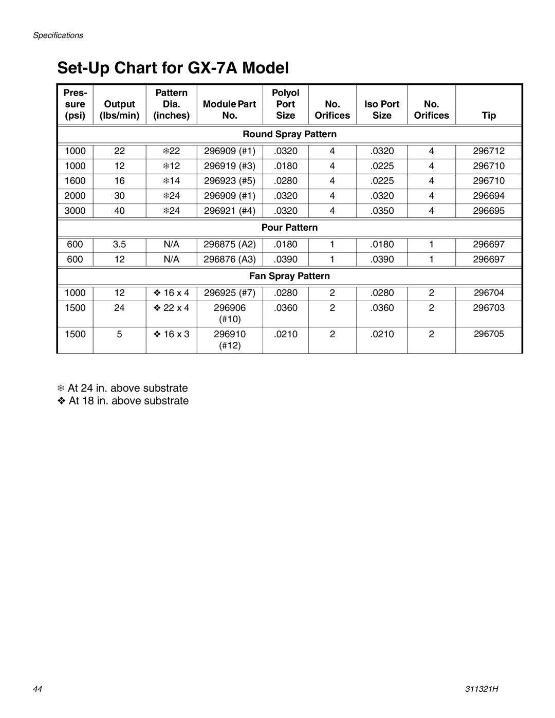
Set-Up Chart for GX-7A Model
Pres- |
| Pattern |
|
| Polyol |
|
|
|
|
sure | Output | Dia. | Module Part |
| Port | No. | Iso Port | No. |
|
(psi) | (lbs/min) | (inches) | No. |
| Size | Orifices | Size | Orifices | Tip |
|
|
|
|
|
|
|
|
| |
|
|
|
|
|
|
| |||
|
|
| Round Spray Pattern |
|
|
| |||
|
|
|
|
|
|
|
|
|
|
|
|
|
|
|
|
|
|
|
|
1000 | 22 | ❄22 | 296909 (#1) |
| .0320 | 4 | .0320 | 4 | 296712 |
|
|
|
|
|
|
|
|
|
|
1000 | 12 | ❄12 | 296919 (#3) |
| .0180 | 4 | .0225 | 4 | 296710 |
|
|
|
|
|
|
|
|
|
|
1600 | 16 | ❄14 | 296923 (#5) |
| .0280 | 4 | .0225 | 4 | 296710 |
|
|
|
|
|
|
|
|
|
|
2000 | 30 | ❄24 | 296909 (#1) |
| .0320 | 4 | .0320 | 4 | 296694 |
|
|
|
|
|
|
|
|
|
|
3000 | 40 | ❄24 | 296921 (#4) |
| .0320 | 4 | .0350 | 4 | 296695 |
|
|
|
|
|
|
|
|
|
|
|
|
|
|
|
|
|
| ||
|
|
|
| Pour Pattern |
|
|
| ||
|
|
|
|
|
|
|
|
|
|
|
|
|
|
|
|
|
|
|
|
600 | 3.5 | N/A | 296875 (A2) |
| .0180 | 1 | .0180 | 1 | 296697 |
|
|
|
|
|
|
|
|
|
|
600 | 12 | N/A | 296876 (A3) |
| .0390 | 1 | .0390 | 1 | 296697 |
|
|
|
|
|
|
|
|
| |
|
|
|
|
|
|
| |||
|
|
| Fan Spray Pattern |
|
|
| |||
|
|
|
|
|
|
|
|
|
|
|
|
|
|
|
|
|
|
|
|
1000 | 12 | ❖ 16 x 4 | 296925 (#7) |
| .0280 | 2 | .0280 | 2 | 296704 |
|
|
|
|
|
|
|
|
|
|
1500 | 24 | ❖ 22 x 4 | 296906 |
| .0360 | 2 | .0360 | 2 | 296703 |
|
|
| (#10) |
|
|
|
|
|
|
|
|
|
|
|
|
|
|
|
|
1500 | 5 | ❖ 16 x 3 | 296910 |
| .0210 | 2 | .0210 | 2 | 296705 |
|
|
| (#12) |
|
|
|
|
|
|
|
|
|
|
|
|
|
|
|
|
❄At 24 in. above substrate
❖ At 18 in. above substrate
44 | 311321H |