Setup
NOTE: HVLP Gun Limits
HVLP Guns: local laws may limit the maximum pressure to 10 psi (70 kPa, 0.7 bar) at the air cap for compliance. See the table on page 8 for maximum HVLP manifold inlet pressures. To measure pressure at the air cap, use the appropriate HVLP Pressure Verification Kit.
L
ti7019a
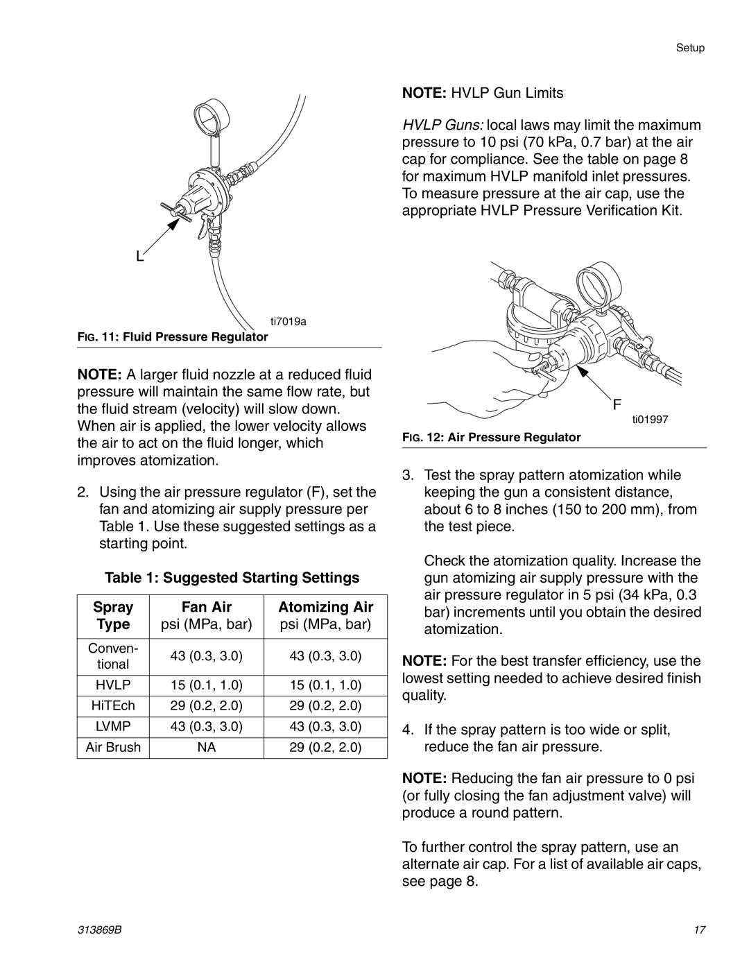
FIG. 11: Fluid Pressure Regulator
NOTE: A larger fluid nozzle at a reduced fluid pressure will maintain the same flow rate, but the fluid stream (velocity) will slow down.
When air is applied, the lower velocity allows the air to act on the fluid longer, which improves atomization.
2.Using the air pressure regulator (F), set the fan and atomizing air supply pressure per Table 1. Use these suggested settings as a starting point.
Table 1: Suggested Starting Settings
Spray | Fan Air | Atomizing Air | |
Type | psi (MPa, bar) | psi (MPa, bar) | |
|
|
| |
Conven- | 43 (0.3, 3.0) | 43 (0.3, 3.0) | |
tional | |||
|
| ||
|
|
| |
HVLP | 15 (0.1, 1.0) | 15 (0.1, 1.0) | |
|
|
| |
HiTEch | 29 (0.2, 2.0) | 29 (0.2, 2.0) | |
|
|
| |
LVMP | 43 (0.3, 3.0) | 43 (0.3, 3.0) | |
|
|
| |
Air Brush | NA | 29 (0.2, 2.0) | |
|
|
|
F
ti01997
FIG. 12: Air Pressure Regulator
3.Test the spray pattern atomization while keeping the gun a consistent distance, about 6 to 8 inches (150 to 200 mm), from the test piece.
Check the atomization quality. Increase the gun atomizing air supply pressure with the air pressure regulator in 5 psi (34 kPa, 0.3 bar) increments until you obtain the desired atomization.
NOTE: For the best transfer efficiency, use the lowest setting needed to achieve desired finish quality.
4.If the spray pattern is too wide or split, reduce the fan air pressure.
NOTE: Reducing the fan air pressure to 0 psi (or fully closing the fan adjustment valve) will produce a round pattern.
To further control the spray pattern, use an alternate air cap. For a list of available air caps, see page 8.
313869B | 17 |