Troubleshooting
240 VAC Filter Board
Perform Pressure Relief Procedure; page 8.
Removal
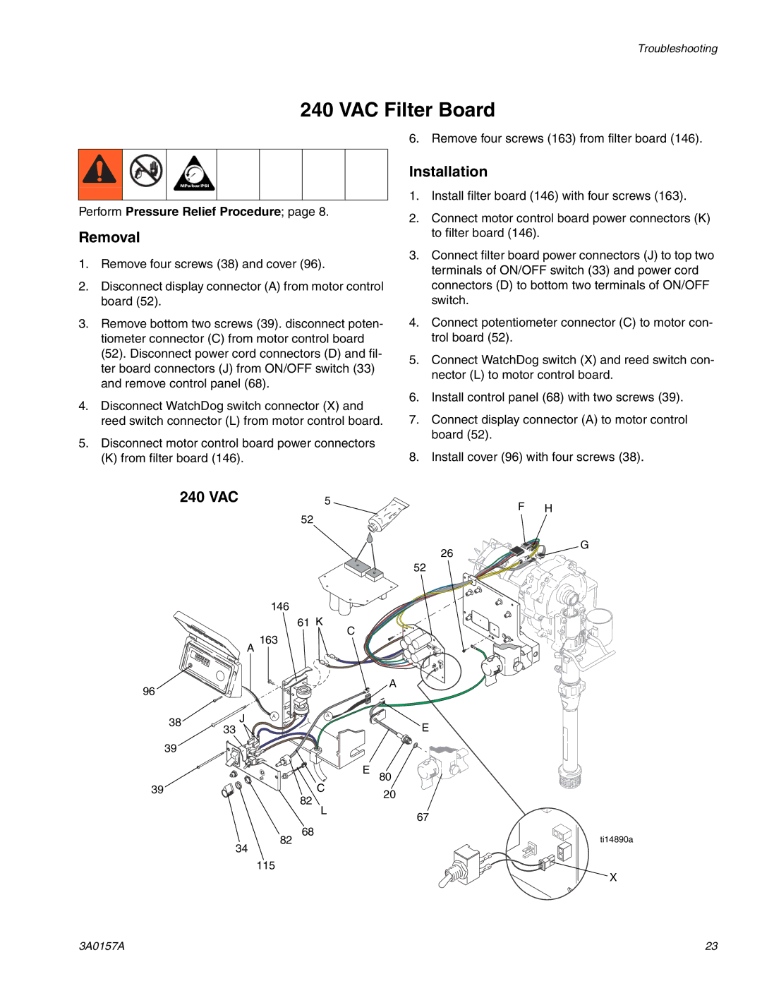
1.Remove four screws (38) and cover (96).
2.Disconnect display connector (A) from motor control board (52).
3.Remove bottom two screws (39). disconnect poten- tiometer connector (C) from motor control board (52). Disconnect power cord connectors (D) and fil- ter board connectors (J) from ON/OFF switch (33) and remove control panel (68).
4.Disconnect WatchDog switch connector (X) and reed switch connector (L) from motor control board.
5.Disconnect motor control board power connectors
(K) from filter board (146).
6. Remove four screws (163) from filter board (146).
Installation
1.Install filter board (146) with four screws (163).
2.Connect motor control board power connectors (K) to filter board (146).
3.Connect filter board power connectors (J) to top two terminals of ON/OFF switch (33) and power cord connectors (D) to bottom two terminals of ON/OFF switch.
4.Connect potentiometer connector (C) to motor con- trol board (52).
5.Connect WatchDog switch (X) and reed switch con- nector (L) to motor control board.
6.Install control panel (68) with two screws (39).
7.Connect display connector (A) to motor control board (52).
8.Install cover (96) with four screws (38).
240 VAC |
| 5 | F H | |
|
|
| 52 | |
|
|
|
| |
|
|
|
| G |
|
|
|
| 26 |
|
|
|
| 52 |
|
| 146 |
|
|
|
|
| 61 K | C |
|
| A 163 |
| |
|
|
|
| |
96 |
|
|
| A |
|
|
|
| |
38 | J | A | A |
|
|
| E | ||
33 |
|
| ||
|
|
| ||
39 |
|
|
|
|
|
|
| C | E 80 |
39 |
|
| 20 | |
|
|
| 82 | |
|
|
|
| |
|
|
| L | 67 |
|
|
|
| |
|
| 82 | 68 | ti14890a |
|
|
| ||
| 34 |
|
| |
115
X
3A0157A | 23 |
