Accessory Assembly - Trapeze support
Assembly Kit# 999-0790-901
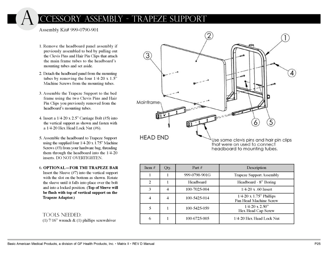
1.Remove the headboard panel assembly if previously assembled to bed by pulling out the Clevis Pins and Hair Pin Clips that attach the main frame tubes to the headboard’s mounting tubes and set aside.
2.Detach the headboard panel from the mounting tubes by removing the four
3.Assemble the Trapeze Support to the bed frame using the two Clevis Pins and Hair Pin Clips you previously removed from the headboard’s mounting tubes.
4.Insert a
5.Assemble the headboard to Trapeze Support using the supplied four
6.
Tools Needed:
(1) 7/16” wrench & (1) phillips screwdriver
Item # | Qty. | Part # | Description | |
|
|
|
| |
1 | 1 | Trapeze Support Assembly | ||
|
|
|
| |
2 | 1 | Headboard | Headboard - 8” Boring | |
|
|
|
| |
3 | 4 | |||
|
|
|
| |
4 | 4 | |||
Pan Head Machine Screw | ||||
|
|
| ||
5 | 1 | |||
Hex Head Cap Screw | ||||
|
|
| ||
6 | 1 | |||
|
|
|
|
Basic American Medical products, a division of GF Health products, Inc. • Matrix II • rev d Manual | p25 |