Roller Spring
Tension
The infeed and outfeed rollers keep the workpiece moving through the planer. There are springs that exert downward pressure on the rollers while still allowing them to raise with an uneven workpiece surface.Properly roller spring tension is crucial to keep the workpiece moving through the planer during operation.
Roller spring tension will vary depending upon the type of wood you are planing. When adjusting the roller spring tension keep the following in mind:
•If you are planing milled lumber with a rela- tively consistent surface, use less spring ten- sion.
•If you are planing rough lumber with incon- sistent surfaces, use greater spring tension to keep the stock moving through the planer.
•If the workpiece consistently stops feeding during operation, the roller spring tension may need to be increased.
Tools Needed | Qty |
Hex Wrench 6mm. | ............................................. 1 |
To adjust the roller spring tension to factory recommendations:
1.DISCONNECT PLANER FROM POWER!
2.Adjust tension cap screws
Cap Screw #4
Cap Screws
Figure 48. Roller spring tension adjustment cap
screws.
G0453/G0454 (Mfg. Since 3/08)
Positioning Chip
Deflector
Chip Deflector Gap Setting | 1⁄4" |
When properly distanced from the cutterhead, direct the chips into the dust hood, and keeps them from falling onto the outfeed roller and being pressed into the workpiece.
Tools Needed | Qty |
Wrench or Socket 10mm | 1 |
Fine Ruler or Calipers | 1 |
To adjust the chip deflector gap: |
|
1.DISCONNECT PLANER FROM POWER!
2.Remove the dust port, top cover, and belt cover.
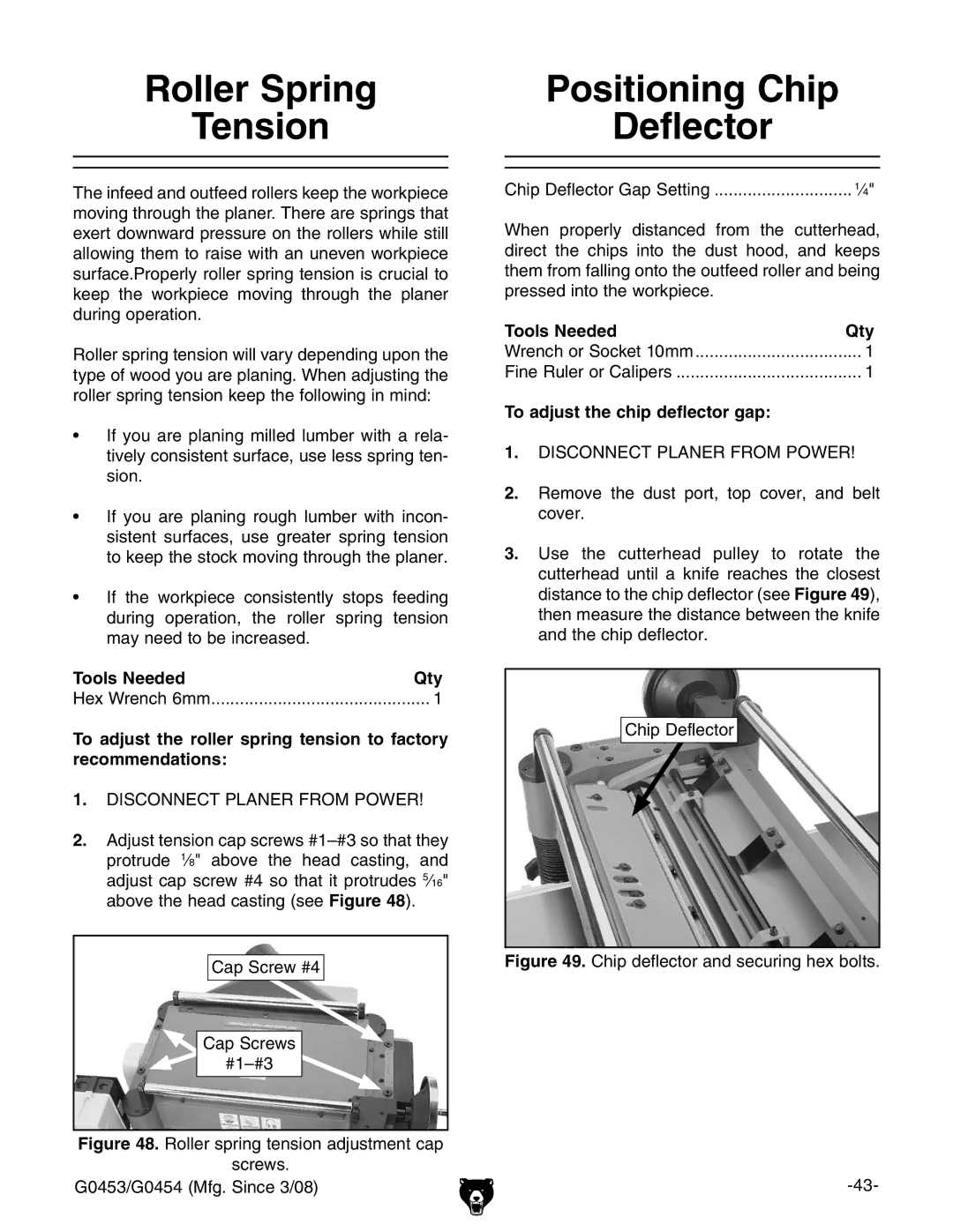
3.Use the cutterhead pulley to rotate the cutterhead until a knife reaches the closest distance to the chip deflector (see Figure 49), then measure the distance between the knife and the chip deflector.
Chip Deflector