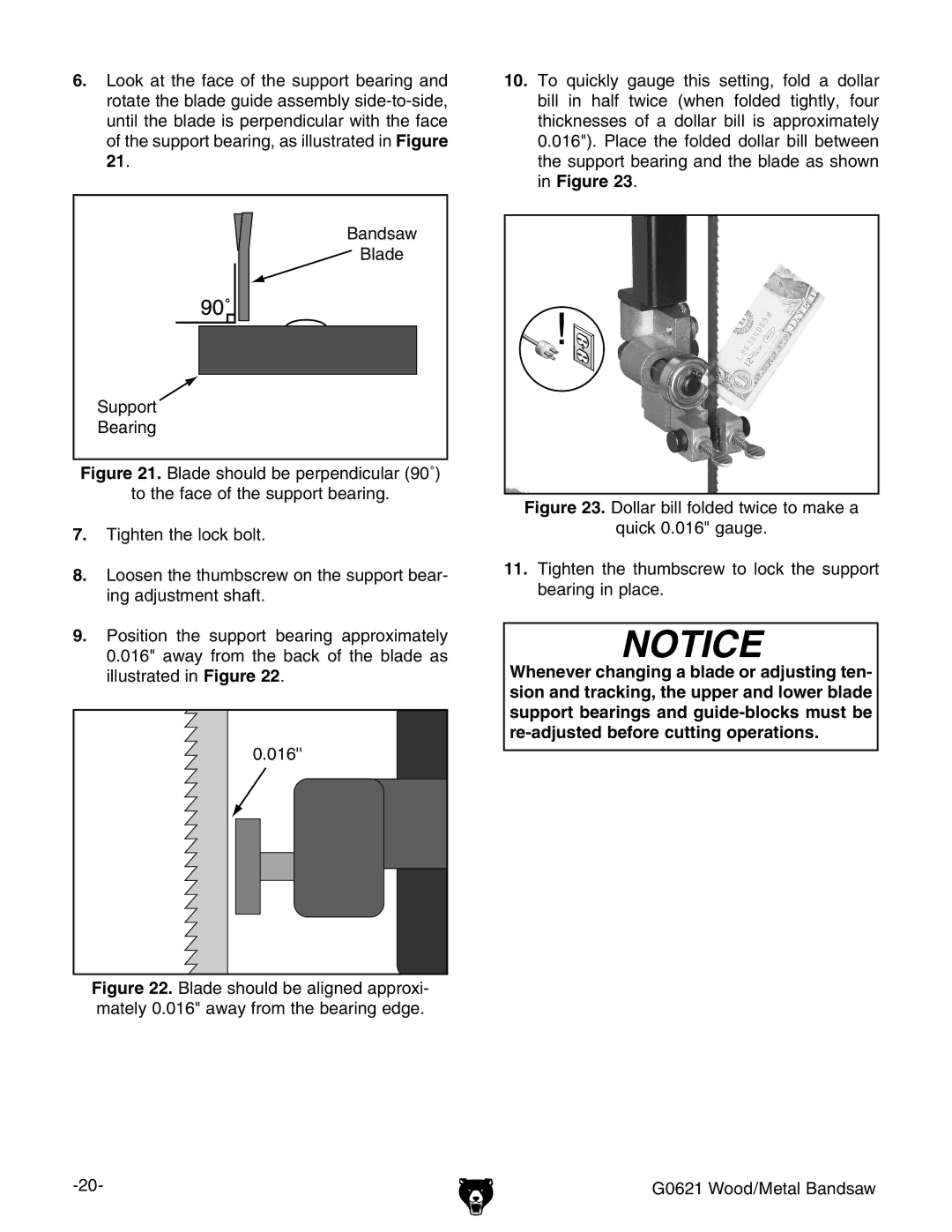
6.Look at the face of the support bearing and rotate the blade guide assembly
�������
![]() �����
�����
�������
�������
Figure 21. Blade should be perpendicular (90˚)
to the face of the support bearing.
7.Tighten the lock bolt.
8.Loosen the thumbscrew on the support bear- ing adjustment shaft.
9.Position the support bearing approximately 0.016" away from the back of the blade as illustrated in Figure 22.
0.016''
Figure 22. Blade should be aligned approxi- mately 0.016" away from the bearing edge.
10.To quickly gauge this setting, fold a dollar bill in half twice (when folded tightly, four thicknesses of a dollar bill is approximately 0.016"). Place the folded dollar bill between the support bearing and the blade as shown in Figure 23.
Figure 23. Dollar bill folded twice to make a
quick 0.016" gauge.
11.Tighten the thumbscrew to lock the support bearing in place.
NOTICE
Whenever changing a blade or adjusting ten- sion and tracking, the upper and lower blade support bearings and
G0621 Wood/Metal Bandsaw |