X- & Y-Axis Handwheels
Use Figure 21 and the following descriptions to become familiar with the X- and
BD
|
| C | |
A | |||
|
| ||
|
| ||
|
|
|
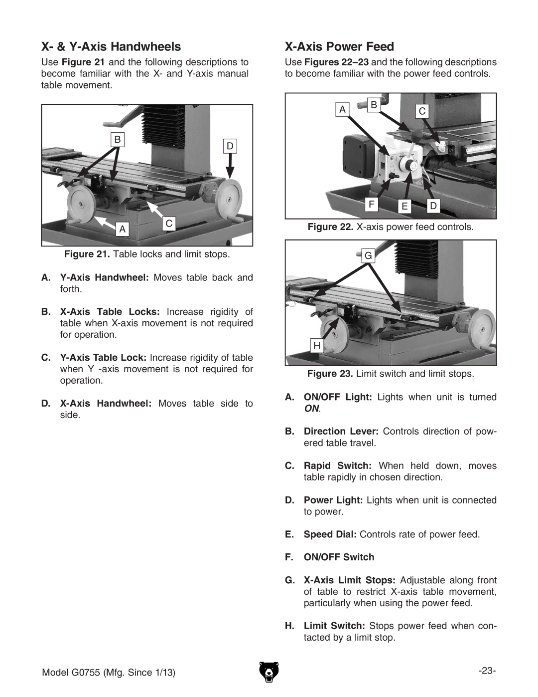
Figure 21. Table locks and limit stops.
A.Y-Axis Handwheel: Moves table back and forth.
B.X-Axis Table Locks: Increase rigidity of table when X-axis movement is not required for operation.
C.Y-Axis Table Lock: Increase rigidity of table when Y -axis movement is not required for operation.
D.X-Axis Handwheel: Moves table side to side.
Model G0755 (Mfg. Since 1/13)
X-Axis Power Feed
Use Figures
A B C
F | E | D |
Figure 22. X-axis power feed controls.
G
H
Figure 23. Limit switch and limit stops.
A.ON/OFF Light: Lights when unit is turned ON.
B.Direction Lever: Controls direction of pow- ered table travel.
C.Rapid Switch: When held down, moves table rapidly in chosen direction.
D.Power Light: Lights when unit is connected to power.
E.Speed Dial: Controls rate of power feed.
F.ON/OFF Switch
G.
H.Limit Switch: Stops power feed when con- tacted by a limit stop.
