Page
Disclaimer
FCC Class a Compliance Statement Canadian Notice
Statement of Agency Compliance
Page
Table of Contents
Page
About This Manual
Getting Started
N344
HHP SET
Getting Started
PC/AT, PS/2 Keyboard Wedge
Keyboard Wedge Interface
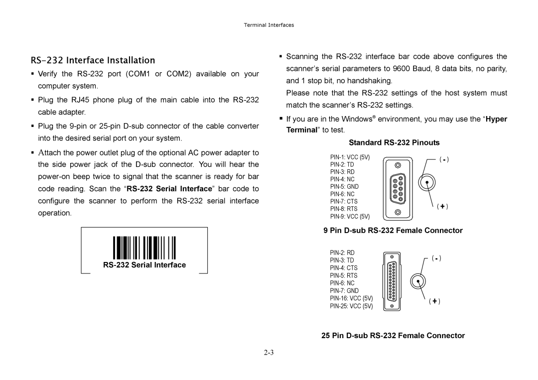
RS-232 Serial Interface
Keyboard Wedge Installation
PS/2 Keyboard Wedge Connection
PC/AT Keyboard Wedge Connection
Pin D-sub RS-232 Female Connector
RS-232 Interface Installation
RS-232 Serial Interface
Standard RS-232 Pinouts
USB Keyboard Interface
USB Keyboard Interface
USB Keyboard Interface Connection
Via HHP SET
Check Software Revision Full-featured Data Editor
Via Bar Code Programming Menu
HHP SET at a Glance
Configuration Download and Upload
Software Installation On-screen Configuration
Program Field Upgrade
Check Software Revision
Data Format Editor
Data Editor
General Transmission Control
Advanced Data Verification
Select Using Match
Configuration Procedure
Application Example
Actual Bar Code label 9 9 1 0 2 5 1 2 3 4 5 6 9 8 7
Programming the Scanner
Programming Procedures
System Command
Bar Code Programming Menu
Family Code
Program & End
System List & Master Default
Example
Selection Flow Diagrams
ENDExit
Host Interface Selection
Host Interface Selection
User Defined Code ID
Symbol ID 1 character
Symbology Programming
Symbol ID 2 character
User Defined Code ID
Symbology Enable
Code ID Transmission and Symbology Enable
Code ID Transmission
Code 39 Family Settings
Code 39/Code 32 Settings
Code 39 Min. Length
Code 39 Max. Length
Codabar Settings
Codabar/NW-7 Setting
Codabar Min. Length
Codabar Max. Length
UPC Family Settings
UPC-A & UPC-E Setting
EAN/CAN/JAN Settings
EAN/JAN/CAN & IATASetting
Iata Settings
Code 2 of 5 Settings
Code 2 of 5 Family & German Post Code Setting
German Postal Setting
Code 2 of 5 Min. Length
Code 11 & Code 93 Setting
MSI/Plessey, Code 128 & UCC/EAN 128 Setting
UK/Plessey & Telepen Setting
Keyboard Interface Control
Keyboard Layout Language Setting
Keyboard Layout
Record Suffix, Preamble, Postamble & Delay Setting
Function Key Emulation
Caps Lock Control & Emulation Setting
Key Pad Emulation
Caps Lock Control
Serial Interface Control
Record Suffix, Handshaking & Time Out Setting
STX/ETX Control
Data Frame
Baud Rate & Data Frame Setting
Time Out Control
Handshaking Protocol
Narrow/Wide Ratio, Code 39 Emulation
Wand Emulation Control
Trigger Modes
Scanning Tolerance Printing Quality Control
Diagnostic Mode Test Reading
Operation Control
Operation Mode
Trigger Mode, Buzzer Tone, Scanning Tolerance
Printing Quality Control
Auto Power Off Duration
Reread Delay
Advanced Operation Control
Pulse Driven Duty
Reread Delay
Reread Delay, Scan Voting
Dollar Sign Control
Scan Voting
Condensed Data Editor
Preamble, Postamble, Data Length & Symbol ID Trans
Data Length Transmission
Data Pass Control
Data Formatter
Data Verifier Settings
1st Replacement
Data Replacer Settings
3rd Replacement
2nd Replacement
Organizer Control
Data Organizer Settings
1st Organization
2nd Organization
Programming Procedure
Select a Bar Code Symbology
Position Calculation
Data Organizer
Data Verifier
Data Replacer
Main Office
Obtaining Factory Service
United Kingdom Office
Japan Office
Asia Pacific Office
Latin America Office
Application Support
Europe
Latin America
Asia
Limited Warranty
Limited Warranty
Appendix a
IllustrationDescription
RS-232 Serial Wedge Cable Converter
Descriptions Beeping Buzzer Tone
Beeping Indications
1DH Down 0EH 1EH Left 0FH 1FH Right
Keyboard Function Code Table
Example
Ascii Input Shortcut
HEX/ASCII Reference Table
Master Default
Bar Code Command Menu
System List
Sample Bar Codes
Factory Default Setting
Bar Code System Command