INSTALLATION
Step Five – Connect the DMC 1000 to a Multizone System (Optional)
The DMC 1000 may be used with up to four zones simultaneously, with any or all zones linked to each other. Zones 2, 3 and 4 are used to distribute
Connect the Analog Audio Outputs for each zone in the system to a receiver, processor, multizone controller or amplifier. See Figure 4 on page 19.
Connect the
Figure 9 – RS-232 Port
Step Six – Connect the Remote IR Input and Output
Connect the DMC 1000’s Remote IR Input to the compatible IR output of another product, or to an IR receiver or controller, such as the optional Harman Kardon HE 1000. When daisychaining devices to allow for remote control up and down the chain, connect the Remote IR Output to the next product’s IR input. See Figure 10. The DMC 1000 is compatible with “stripped carrier” IR signals.
end into an unswitched AC outlet. Due to the DMC 1000’s power require- ments, do not plug it into an accessory outlet on another component.
Figure 12 – Master Power Switch and AC Power Input
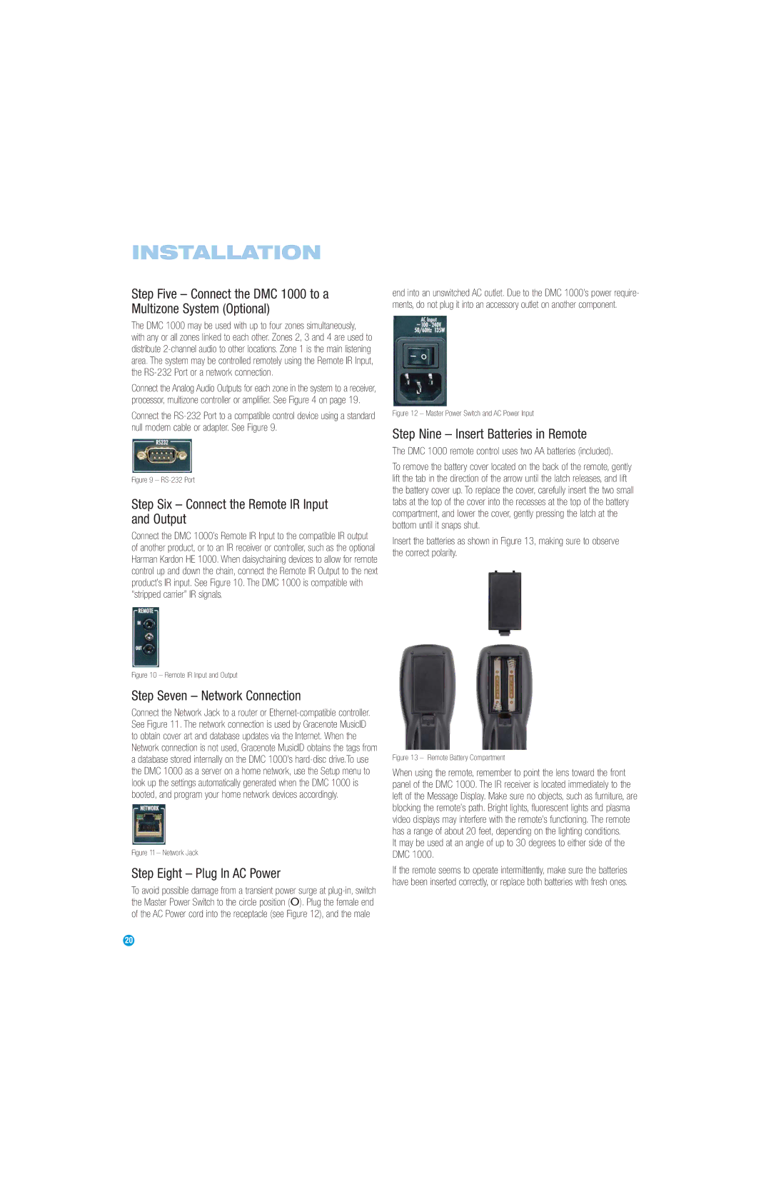
Step Nine – Insert Batteries in Remote
The DMC 1000 remote control uses two AA batteries (included).
To remove the battery cover located on the back of the remote, gently lift the tab in the direction of the arrow until the latch releases, and lift the battery cover up. To replace the cover, carefully insert the two small tabs at the top of the cover into the recesses at the top of the battery compartment, and lower the cover, gently pressing the latch at the bottom until it snaps shut.
Insert the batteries as shown in Figure 13, making sure to observe the correct polarity.
Figure 10 – Remote IR Input and Output
Step Seven – Network Connection
Connect the Network Jack to a router or
Figure 11 – Network Jack
Step Eight – Plug In AC Power
To avoid possible damage from a transient power surge at
Figure 13 – Remote Battery Compartment
When using the remote, remember to point the lens toward the front panel of the DMC 1000. The IR receiver is located immediately to the left of the Message Display. Make sure no objects, such as furniture, are blocking the remote’s path. Bright lights, fluorescent lights and plasma video displays may interfere with the remote’s functioning. The remote has a range of about 20 feet, depending on the lighting conditions.
It may be used at an angle of up to 30 degrees to either side of the DMC 1000.
If the remote seems to operate intermittently, make sure the batteries have been inserted correctly, or replace both batteries with fresh ones.
20