R
3100 Wood Stove Series (ACC)
Thimble
Site constructed for masonry chimney installation:
Components
•A minimum length of 12 inches [305mm] (longer for thicker walls) of solid insulated
•Wall spacer, trim collar and wall band to fit solid pack chimney selected.
•Minimum 8 inch (203mm) diameter clay liner section (if not already present in chimney) and refractory mortar.
Air Clearances
•Masonry chimney clearance must meet NFPA 211 mini- mum requirement of 2 inches (51mm) to sheet metal supports and combustibles.
•Minimum of 1 inch (25mm) clearance around the chim- ney connector.
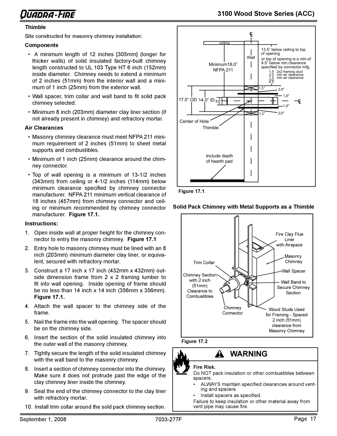
•Top of wall opening is a minimum of
Instructions:
C
L
| ceiling |
| 13.5” below ceiling to top | ||||||||
|
|
|
|
|
| ||||||
|
|
|
|
| Wall | of opening | |||||
|
|
|
|
| or top of opening is a min.of | ||||||
Minimum18.0” | 4.5” below min.clearance | ||||||||||
NFPA 211 | specified by connector mfg. | ||||||||||
1.5 | 2x2 framing stud | ||||||||||
|
|
|
|
|
| 2.0 | min air clearance | ||||
|
|
|
|
|
| 1.0 | min air clearance | ||||
|
|
|
|
|
| 4.5 |
|
|
|
| |
|
|
|
|
|
| 1.5” |
| 2.0” | |||
|
|
|
|
|
|
| |||||
|
|
|
|
|
|
|
| ||||
17.0” OD 14.0” ID |
|
|
|
|
|
|
|
|
| 1.0” | |
|
|
|
|
|
|
|
|
| |||
|
|
|
|
|
|
|
|
| |||
8.0” |
|
|
|
|
|
| C | ||||
|
|
|
|
|
|
|
|
|
| L | |
|
|
|
|
|
|
|
|
|
| 1.0” | |
|
|
|
|
|
| 1.5” | 2.0” | ||||
|
|
|
|
|
| ||||||
Center of Hole | |||||||||||
|
|
|
|
| |||||||
Thimble |
|
|
|
|
| ||||||
Include depth of hearth pad
Figure 17.1
Solid Pack Chimney with Metal Supports as a Thimble
1. | Open inside wall at proper height for the chimney con- |
| nector to entry the masonry chimney. Figure 17.1 |
2. | Entry hole to masonry chimney must be lined with an 8 |
| inch (203mm) minimum diameter clay liner, or equiva- |
| lent, secured with refractory mortar. |
3. | Construct a 17 inch x 17 inch (432mm x 432mm) out- |
| side dimension frame from 2 x 2 framing lumber to |
| fit into wall opening. Inside opening of frame should |
| be no less than 14 inch x 14 inch (356mm x 356mm). |
| Figure 17.1. |
4. | Attach the wall spacer to the chimney side of the |
| frame. |
5. | Nail the frame into the wall opening. The spacer should |
| be on the chimney side. |
6. | Insert the section of the solid insulated chimney into |
Trim Collar
Chimney Section
with 2 inch
(51mm)
Clearance to Combustibles
Chimney
Connector
Fire Clay Flue
Liner
with Airspace
Masonry
Chimney
Wall Spacer
Wall Band to
Secure Chimney
Section
Wood Studs Used
for Framing - Spaced
2 inch (51mm) clearance from Masonry Chimney
the outer wall of the masonry chimney. |
Figure 17.2
7. | Tightly secure the length of the solid insulated chimney |
| WARNING | |
| with the wall band to the masonry chimney. |
|
|
|
|
|
| Fire Risk. | |
8. | Insert a section of chimney connector into the chimney. |
| ||
| Make sure it does not protrude past the edge of the |
| Do NOT pack insulation or other combustibles between | |
|
| spacers. | ||
| clay chimney liner inside the chimney. |
|
| |
|
|
| • ALWAYS maintain specified clearances around vent- | |
9. | Seal the end of the chimney connector to the clay liner |
| ing and spacers. | |
| with refractory mortar. |
|
| • Install spacers as specified. |
|
|
| Failure to keep insulation or other material away from | |
10. Install trim collar around the sold pack chimney section. |
| |||
| vent pipe may cause fire. | |||
|
|
|
| |
|
|
|
|
|
|
|
|
| |
September 1, 2008 |
| Page 17 | ||
