Owner’s Manual
Models SL-550TV-IPI-E SL-750TV-IPI-E SL-950TV-IPI-E
What to do if you smell gas
Homeowner Reference Information
A. Congratulations
Read this manual before installing or operating this appliance
Please retain this owner’s manual for future reference
Safety Alert Key
Table of Contents
Installer Guide
3 Maintenance and Service
15 Troubleshooting
14 Appliance Setup
A. Remove Glass Assembly B. Remove the Shipping Materials
C. Clean the Appliance D. Accessories
CONDITIONS, EXCLUSIONS & LIMITATION OF LIABILITY
B. Limited Lifetime Warranty
Hearth & Home Technologies LIMITED WARRANTY
B. Limited Lifetime Warranty continued
A. Appliance Certification
1 Listing and Code Approvals
B. Tempered Glass Specifications
C. BTU Specifications
E. Non-Combustible Materials Specification
D. High Altitude Installations
F. Combustible Materials Specification
G. Electrical Codes
B. Your Fireplace
A. Gas Fireplace Safety
2 Operating Instructions User Guide
G. Remote Controls, Wall Controls and Wall Switches
F. Fixed Glass Assembly
C. Fan Kit optional
E. Decorative Doors and Fronts
Final inspection by
I. Lighting Instructions IPI
FOR YOUR SAFETY READ BEFORE LIGHTING
1. Turn off all electric power to the appliance
J. After Fireplace is Lit
K. Frequently Asked Questions
ISSUE
SOLUTIONS
A. Maintenance Tasks-Homeowner
3 Maintenance and Service
Glass Cleaning
Remote Control
Gasket Seal and Glass Assembly Inspection
B. Maintenance Tasks-Qualified Service Technician
Venting
Logs
Figure 3.2 IPI Pilot Flame Patterns
Either cobrahead or SIT
A. Typical Appliance System
Getting Started
Installer Guide
FRAMING HEADED OFF IN CEILING JOISTS SECTION 8.B OPTIONAL WALL SWITCH
D. Inspect Appliance and Components
B. Design and Installation Considerations
C. Tools and Supplies Needed
E. Negative Pressure
A. Selecting Appliance Location
5 Framing and Clearances
F A
Model
MINIMUM FRAMING DIMENSIONS
B. Constructing the Appliance Chase
C. Clearances
Combustible Mantels
D. Mantel and Wall Projections
Note All measurements are in inches
Figure 5.4 Non-Combustible Zone
A. Vent Termination Minimum Clearances
6 Termination Locations
Fire Risk Maintain vent clearance to combustibles as specified
DO NOT pack air space with insulation or other materials
A. Vent Guidelines
7 Vent Information and Diagrams
B. Vent System Configuration
Vent this appliance directly outside
A. Pipe Clearances to Combustibles
8 Vent Clearances and Framing
B. Wall and Ceiling Penetration Framing
C. Vertical Penetration Framing
9 Appliance Preparation
A. Installing Outside Air Kit Damper Assem- bly
B. Gas and Electrical Connections
C. Securing and Leveling the Appliance
A. Assembly of Vent Sections
10 Installing Vent Pipe
D. Install Attic Insulation Shield
C. Securing Vent Sections
A. Fuel Conversion
11 Gas Information
B. Gas Pressure
C. Gas Connection
C. Optional Accessories Requirements
A. Wiring Requirements
D. Electrical Service and Repair
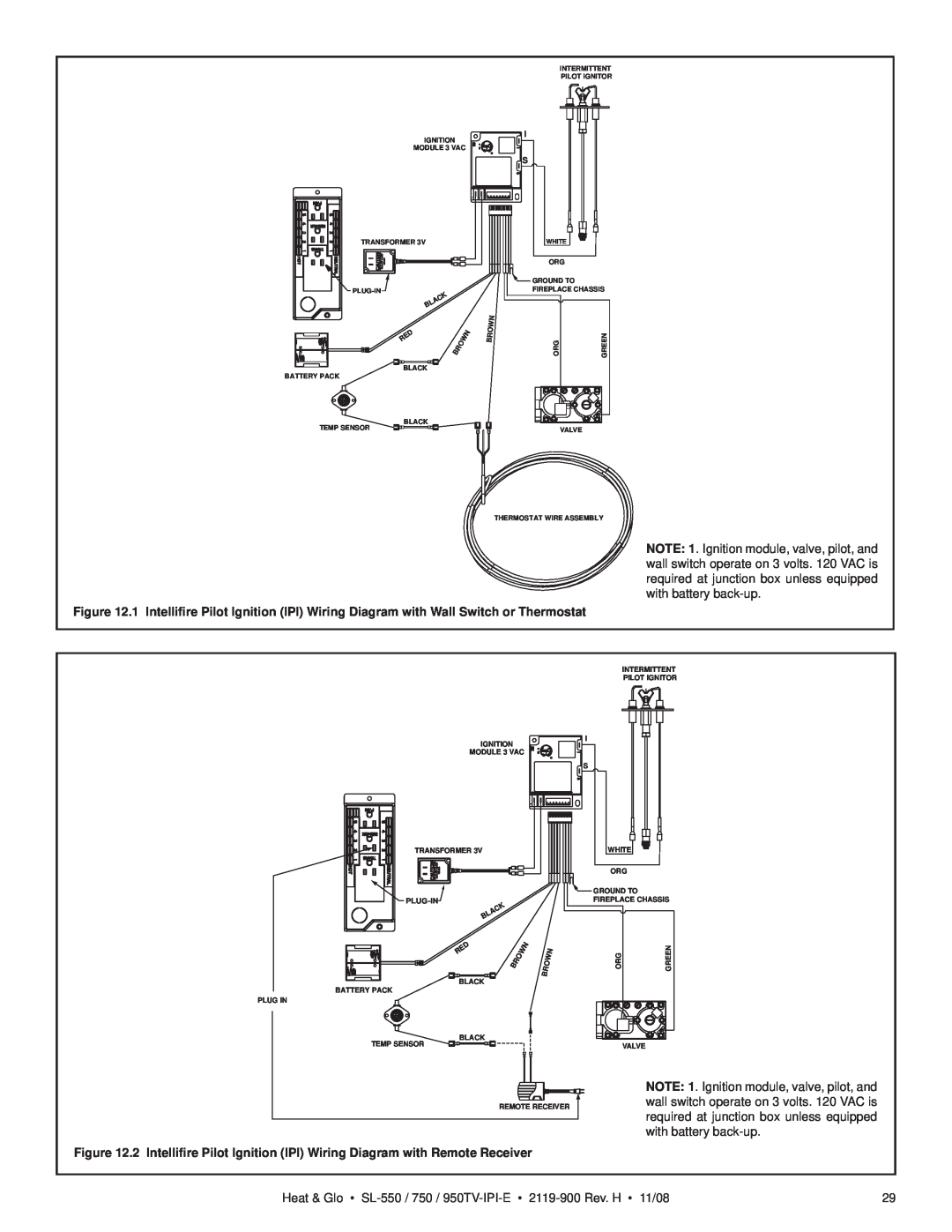
B. Intellifire Ignition System Wiring
BROWN
F. Wall Switch Installation for Fan Optional
E. Junction Box Installation
NOTICE DO NOT wire
110 VAC to wall switch
A. Mantel and Wall Projections
13 Finishing
Dimensions of Combustibles
Dimensions of Non-Combustibles
B. Facing Material
A. Remove Glass Assembly
14 Appliance Setup
C. Clean the Appliance
D. Accessories
Placing the Lava Rock
E. Lava Rock, Mineral Wool/Ember Placement
Model SL-550TR-E, 750TR-E, 950TR-E SL-550TV-E, SL-750TV-E, SL-950TV-E
F. Install the Log Assembly
Log Set Assembly LOGS-550-E, 750-E, 950-E
Log #3 Locate the pin hole on the underside of log #3. Mate the pin hole with the shoulder screw located on the burner top. Push the left end of log # 3 toward the back of the firebox until it touches the lava rock retainer
H. Install the Mesh
G. Fixed Glass Assembly
I. Install Trim and/or Surround
J. Install Hood
A. Intellifire Ignition System
15 Troubleshooting
Symptom
A. Incorrect wiring
Symptom
Intellifire Ignition System - continued
Verify all connections to wiring diagram in manual. Verify
With fixed glass assembly in place, verify that flame is en
16 Reference Materials
A. Appliance Dimension Diagram
Figure 16.1 Appliance Dimensions
GAS LINE ACCESS
B. Service Parts
Log Set Assembly
SL-550TV-IPI-E
Service Parts Diagram
SL-550TV-IPI-E
Service Parts List
at Depot
Stocked
SL-750TV-IPI-E
Service Parts
Log Set Assembly
Service Parts Diagram
SL-750TV-IPI-E
Service Parts List
at Depot
Stocked
Log Set Assembly
SL-950TV-IPI-E
Service Parts
Service Parts Diagram
Stocked
SL-950TV-IPI-E
Service Parts List
at Depot
Service Parts
IPI Valve Assembly
SL-550 / 750 / 950TV-IPI-E
Stocked
and maintenance
C. Contact Information
installation and operation
DO NOT DISCARD THIS MANUAL