Heat CONTROLLER, INC
Table of Contents
KBtu/h 2 rooms
Symbols Used in this Manual
KBtu/h 3 rooms
Be sure not to do Be sure to follow the instruction
Safety Precautions
Installation
Control box securely Cuit and breaker
Defective installation stand
Do not install, remove, or re
Do not install the product on a
Do not allow water to run into electric parts
Never enter the product
When the product is soaked Be cautious that water can
Flooded or submerged, contact
Installing the product
Install the drain hose to ensure that Keep level even when
Use two or more people to lift and transport the product
Operational
Do not use the remote is the batteries have leaked
Seaside applications and installation
Selecting the locationOutdoor Unit
Indoor Unit
Dimensions
Split Type Indoor
Outdoor Unit
18kBtu/h
24kBtu/h
UE2
36kBtu/h
Product Specifications
Indoor Unit Type Wall Mounted Model
Outdoor Unit Multiple piping models
MMC18FA-1 MMH18FA-1
MMC24FA-1 MMH24FA-1
MMC36FA-1 MMH36FA-1
Installation Parts
Installation
Installation Tools
Selecting the best location
Multi Piping Type
Piping length and elevation
18 / 24 kBtu/h KBtu/h
Installing Installation PlateStandard Type
Drilling the hole in the wall
Flaring Work and Connection of Piping
Flaring work
Check
Connecting the Piping
Indoor
Indoor unit installation
Wrap the insulation material around the all connections
For left rear piping
Wrap the insulation material around the connecting por- tion
Good case
Bad case
Remote Control Preparationoptional
Outdoor unit 18/24 kBtu/h
Outdoor
Outdoor unit 36 kBtu/h
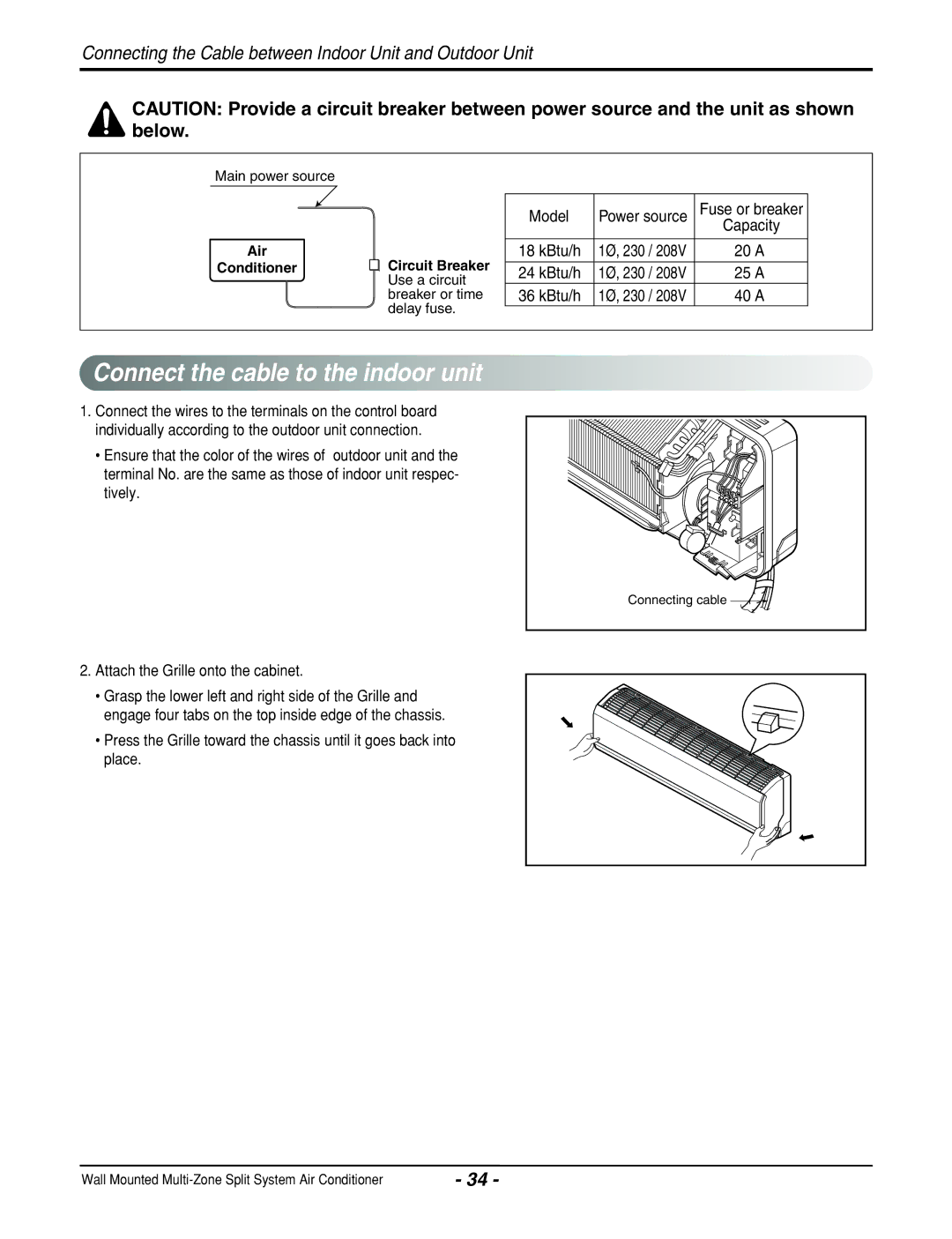
Connect the cable to the Indoor unit
Tions ETL recognized and CSA certified
Connect the cable to the Outdoor unit
Outdoor unit
Methods of connecting the cable
How to connect wiring to the terminals
Model
To check the drainage
Checking the drainage
Drain piping
Secure the taped piping along the exterior wall using
Insulating the Pipe and Special Piping Applications
Preparation
Air Purging and Evacuation
Leak checking
Leakage test
Evacuation
Repeat evacuation procedure for each indoor unit
Finishing the job
Charging
Additional
Test Running
Split Type
Heating Mode Operation
Cooling Mode Operation
Soft Dry Operation Mode
Operation
Fuzzy Operation
Defrost ControlHeating
Fuzzy Operation for Cooling
Airflow Speed Selection
On-Timer Operation
Off-Timer Operation
Fuzzy Operation for Dehumidification
Chaos Swing Mode
Off-Timer = On-Timer Operation
Sleep Timer Operation
Chaos Natural Wind Mode
Forced Operation
Buzzer Sound
Function of Indoor Unit
Split Type Indoor Unit
Function of Outdoor Unit
Time Setting Buttons Used to adjust the time
Remote Control Operation
Cooling Model , Heat Pump Model
Disassembly
To remove the Grille from the Chassis
To remove the Control Box
To remove the Motor Cover
Electronic Control Device
Schematic Diagram
Indoor Unit
Outdoor Unit
TMP87CM41F
RY-4WAY RY-LIQ RY-GAS RY-FANL RY-FANH
Wiring Diagram
Indoor Unit Outdoor Unit
MMC24FA-1
Component Locations
Bottom View
Display Assembly Split Type 6871A20680
Component side
Solder side
MMC18FA-1
Troubleshooting Guide
Refrigeration Cycle Diagram
MMH18FA-1
MMH24FA-1
MMC36FA-1
MMH36FA-1
Error Indicator
Indoor Error
Outdoor Error
Self-diagnosis Function
Cycle Troubleshooting Guide
Trouble analysis
Electronic Parts Troubleshooting Guide
Procedure Specification Remedy
Product doesnt operate with the remote controller
Compressor/Outdoor Fan dont operate
Check Point Comp. on Comp. OFF
Trouble 4 When indoor Fan does not operate
Nector
Voltage of Connectors according to Indoor Fan Speed
RY-COMP-B
When Vertical Louver does not operate
Indoor air sensor
Error Code
Check Point
Indoor inlet pipe sensor
Power input AC 230V.Outdoor, Indoor
Description Cause of error Check point & Normal condition
Communication line is shorted at GND
Comp OFF
Condensor pipe sensor
Outdoor air sensor
Pipe sensor
Way, 3-way Valve
Way Valve Liguid Side
Procedure
Pumping down
Evacuation
Replace the valve and service port caps
All the refrigerant leaked
After Evacuation
Replace the valve stem nuts and the service port nut
Gas Charging
Connect the gauge to the charging cylinder
Exploded View
Model B-MMC09FA-1, B-MMH09FA-1, B-MMC12FA-1, B-MMH12FA-1
Model A-MMC18FA-1, A-MMH18FA-1
Model A-MMC24FA-1, A-MMH24FA-1
Model A-MMC36FA-1, A-MMH36FA-1
Heat CONTROLLER, INC
08/06/2008


 Connect
 the
the cable to
 the
the indoor
 unit
unit