Model
2-8. FLAME SENSOR/ PILOT / IGNITOR ASSEMBLY (Gas) (Continued)
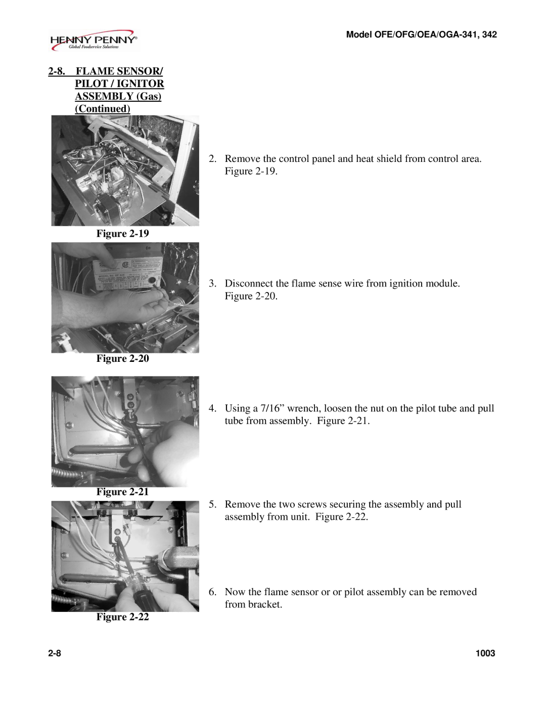
2.Remove the control panel and heat shield from control area. Figure
Figure
3.Disconnect the flame sense wire from ignition module. Figure
Figure
4.Using a 7/16” wrench, loosen the nut on the pilot tube and pull tube from assembly. Figure
Figure
5.Remove the two screws securing the assembly and pull assembly from unit. Figure
6.Now the flame sensor or or pilot assembly can be removed from bracket.
Figure
1003 |