4. How to use the vise assembly
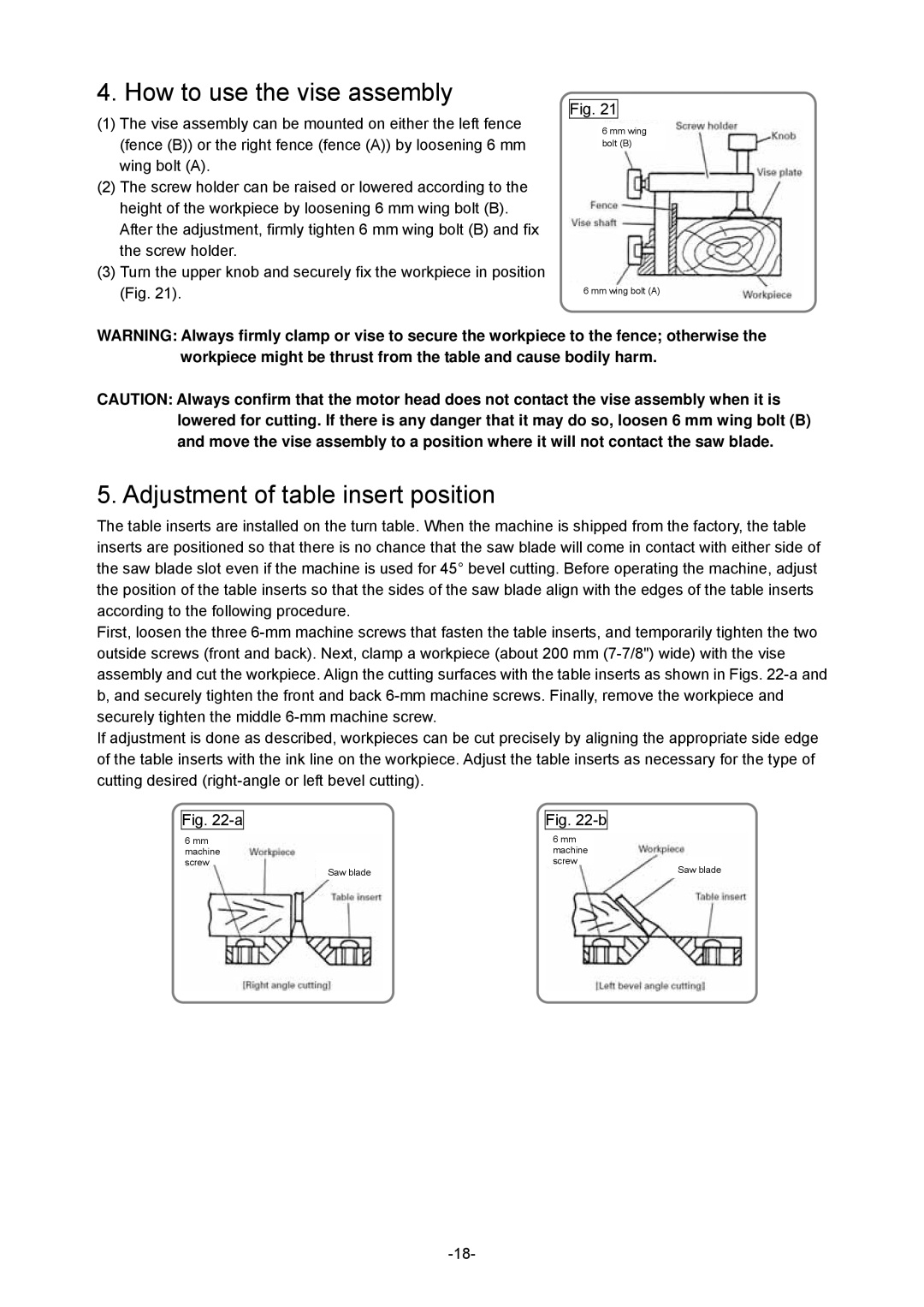
(1)The vise assembly can be mounted on either the left fence (fence (B)) or the right fence (fence (A)) by loosening 6 mm wing bolt (A).
(2)The screw holder can be raised or lowered according to the height of the workpiece by loosening 6 mm wing bolt (B). After the adjustment, firmly tighten 6 mm wing bolt (B) and fix the screw holder.
(3)Turn the upper knob and securely fix the workpiece in position (Fig. 21).
Fig. 21
6 mm wing bolt (B)
6 mm wing bolt (A)
WARNING: Always firmly clamp or vise to secure the workpiece to the fence; otherwise the workpiece might be thrust from the table and cause bodily harm.
CAUTION: Always confirm that the motor head does not contact the vise assembly when it is lowered for cutting. If there is any danger that it may do so, loosen 6 mm wing bolt (B) and move the vise assembly to a position where it will not contact the saw blade.
5. Adjustment of table insert position
The table inserts are installed on the turn table. When the machine is shipped from the factory, the table inserts are positioned so that there is no chance that the saw blade will come in contact with either side of the saw blade slot even if the machine is used for 45° bevel cutting. Before operating the machine, adjust the position of the table inserts so that the sides of the saw blade align with the edges of the table inserts according to the following procedure.
First, loosen the three
If adjustment is done as described, workpieces can be cut precisely by aligning the appropriate side edge of the table inserts with the ink line on the workpiece. Adjust the table inserts as necessary for the type of cutting desired
Fig.
6mm machine screw
Saw blade
Fig.
6mm machine screw
Saw blade
