6. Laser marker
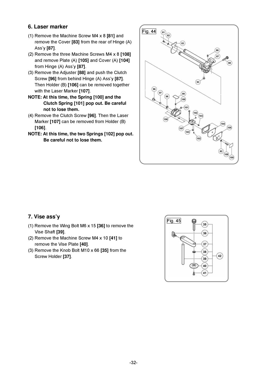
(1)Remove the Machine Screw M4 x 8 [81] and remove the Cover [83] from the rear of Hinge (A) Ass’y [87].
(2)Remove the three Machine Screws M4 x 8 [108] and remove Plate (A) [105] and Cover (A) [104] from Hinge (A) Ass’y [87].
(3)Remove the Adjuster [88] and push the Clutch Screw [96] from behind Hinge (A) Ass’y [87]. Then Holder (B) [106] can be removed together
with the Laser Marker [107].
NOTE: At this time, the Spring [100] and the Clutch Spring [101] pop out. Be careful not to lose them.
(4)Remove the Clutch Screw [96]. Then the Laser Marker [107] can be removed from Holder (B)
[106].
NOTE: At this time, the two Springs [102] pop out. Be careful not to lose them.
Fig. 44
7. Vise ass’y
(1)Remove the Wing Bolt M6 x 15 [36] to remove the Vise Shaft [39].
(2)Remove the Machine Screw M4 x 10 [41] to remove the Vise Plate [40].
(3)Remove the Knob Bolt M10 x 66 [35] from the Screw Holder [37].
Fig. 45
