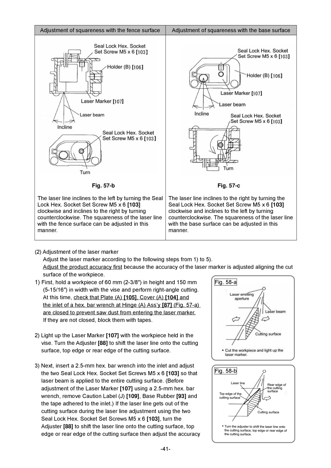
Adjustment of squareness with the fence surface
Adjustment of squareness with the base surface
Fig.
The laser line inclines to the left by turning the Seal Lock Hex. Socket Set Screw M5 x 6 [103] clockwise and inclines to the right by turning counterclockwise. The squareness of the laser line with the fence surface can be adjusted in this manner.
Fig.
The laser line inclines to the right by turning the Seal Lock Hex. Socket Set Screw M5 x 6 [103] clockwise and inclines to the left by turning counterclockwise. The squareness of the laser line with the base surface can be adjusted in this manner.
(2)Adjustment of the laser marker
Adjust the laser marker according to the following steps from 1) to 5).
Adjust the product accuracy first because the accuracy of the laser marker is adjusted aligning the cut surface of the workpiece.
1) First, hold a workpiece of 60 mm | Fig. |
| |
At this time, check that Plate (A) [105], Cover (A) [104] and |
|
the inlet of a hex. bar wrench at Hinge (A) Ass’y [87] (Fig. |
|
are closed to prevent saw dust from entering the laser marker. |
|
If they are not closed, block them with tapes. |
|
2) Light up the Laser Marker [107] with the workpiece held in the |
|
vise. Turn the Adjuster [88] to shift the laser line onto the cutting |
|
surface, top edge or rear edge of the cutting surface. |
|
3) Next, insert a |
|
the two Seal Lock Hex. Socket Set Screws M5 x 6 [103] so that | Fig. |
| |
laser beam is applied to the entire cutting surface. (Before |
|
adjustment of the Laser Marker [107] using a |
|
wrench, remove Caution Label (J) [109], Base Rubber [93] and |
|
the tape adhered to the inlet.) If the laser line gets out of the |
|
cutting surface during the laser line adjustment using the two |
|
Seal Lock Hex. Socket Set Screws M5 x 6 [103], turn the |
|
Adjuster [88] to shift the laser line onto the cutting surface, top |
|
edge or rear edge of the cutting surface then adjust the accuracy |
|
|