2. Lower guard, link, spindle ass'y and dust guide
(1)Remove the Bolt (W/Washers) M6 x 16 (Black) [207] and the Machine Screws (W/Washers) M5 x 8
[191]with the Box Wrench 10 mm [501]. Remove the Spindle Cover [192] from the Gear Case [198].
(2)Remove the Bolt (Left Hand) W/Washer M7 x 17.5 [210] with the Box Wrench 10 mm [501]. Remove Washer (D) [221], TCT Saw Blade [211] and Washer (D) [221] in this order from the Spindle Ass’y
(3)Remove the two Flat Hd. Screws M4 x 10 [213]. Remove the Cover [214] and the Lower Guard [215] from the Bearing Holder [219].
NOTE: Be sure to release the hook of the Return Spring [216] from the groove of the Lower Guard
[215]then remove the Lower Guard [215] from the Bearing Holder [219].
(4)Remove the Machine Screw M5 x 12 [89] then remove the Spacer [90] and the Link [91] from Hinge (A) Ass’y [87].
(5)Remove the two Machine Screws M5 x 20 [222] and then remove the Spindle Ass'y [217] by gently hammering the Gear Case [198] with a plastic hammer.
(6)Remove the Machine Screws (W/Washers) M4 x 12 (Black) [194] and then remove the Dust Guide
[208]and the Guide Holder [209].
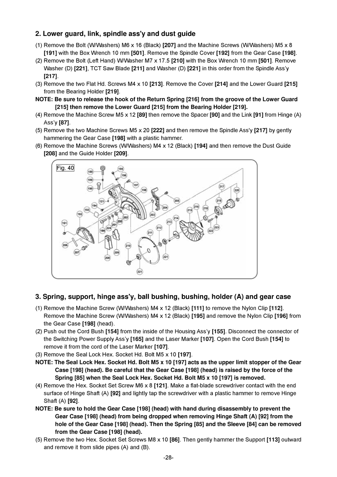
Fig. 40
3. Spring, support, hinge ass'y, ball bushing, bushing, holder (A) and gear case
(1)Remove the Machine Screw (W/Washers) M4 x 12 (Black) [111] to remove the Nylon Clip [112]. Remove the Machine Screw (W/Washers) M4 x 12 (Black) [195] and remove the Nylon Clip [196] from the Gear Case [198] (head).
(2)Push out the Cord Bush [154] from the inside of the Housing Ass’y [155]. Disconnect the connector of the Switching Power Supply Ass’y [165] and the Laser Marker [107]. Open the Cord Bush [154] to remove it from the cord of the Laser Marker [107].
(3)Remove the Seal Lock Hex. Socket Hd. Bolt M5 x 10 [197].
NOTE: The Seal Lock Hex. Socket Hd. Bolt M5 x 10 [197] acts as the upper limit stopper of the Gear Case [198] (head). Be careful that the Gear Case [198] (head) is raised by the force of the Spring [85] when the Seal Lock Hex. Socket Hd. Bolt M5 x 10 [197] is removed.
(4) Remove the Hex. Socket Set Screw M6 x 8 [121]. Make a
NOTE: Be sure to hold the Gear Case [198] (head) with hand during disassembly to prevent the Gear Case [198] (head) from being dropped when removing Hinge Shaft (A) [92] from the hole of the Gear Case [198] (head). Then the Spring [85] and the Sleeve [84] can be removed from the Gear Case [198] (head).
(5)Remove the two Hex. Socket Set Screws M8 x 10 [86]. Then gently hammer the Support [113] outward and remove it from slide pipes (A) and (B).