9 | SMARTBOX Installation |
|
|
|
|
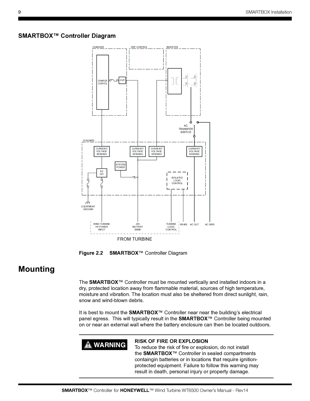
SMARTBOX™ Controller Diagram
CHARGER | DSP CONTROL |
CHARGE ![]()
![]()
![]() OVP
OVP
CONTOL
IO BOARD
INVERTER |
AC |
TRANSFER |
SWITCH |
CURRENT/ | CURRENT/ | CURRENT/ |
|
| CURRENT/ |
|
VOLTAGE | VOLTAGE | VOLTAGE |
|
| VOLTAGE |
|
SENSING | SENSING | SENSING |
|
| SENSING |
|
| SYSTEM |
|
|
|
|
|
| POWER |
|
|
|
|
|
DC |
|
|
|
|
|
|
GFI |
|
|
|
|
|
|
|
|
| ISOLATED |
|
| |
|
|
| LOGIC |
|
| |
|
|
| CONTROL |
|
| |
EQUIPMENT |
|
|
|
|
|
|
GROUND |
|
|
|
|
|
|
WIND TURBINE | 24V |
| TURBINE | RS485 | AC OUT | AC GRID |
HV POWER | BATTERY |
| LOGIC |
|
|
|
INPUT | BANK |
| CONTROL |
|
|
|
FROM TURBINE
Figure 2.2 SMARTBOX™ Controller Diagram
Mounting
The SMARTBOX™ Controller must be mounted vertically and installed indoors in a dry, protected location away from flammable material, sources of high temperature, moisture and vibration. The location must also be sheltered from direct sunlight, rain, snow and
It is best to mount the SMARTBOX™ Controller near near the building’s electrical panel egress. This will typically result in the SMARTBOX™ Controller being mounted on or near an external wall where the battery enclosure can then be located outdoors.
RISK OF FIRE OR EXPLOSION
To reduce the risk of fire or explosion, do not install the SMARTBOX™ Controller in sealed compartments containgin batteries or in locations that require ignition- protected equipment. Failure to follow this warning may result in death, personal injury or property damage.
SMARTBOX™ Controller for HONEYWELL™ Wind Turbine WT6500 Owner’s Manual - Rev14