SMARTBOX Installation | 20 |
|
|
|
|
Enclosure Internal Wiring
NEC/CEC and UL require that no wires cross within the Junction Box. Punch outs have been provided on the bottom of the Junction Box to meet this requirement.
Battery Setup
FIRE HAZARD
Batteries must be set correctly to avoid explosion or fire. Failure to follow this warning may result in death, personal injury or property damage.
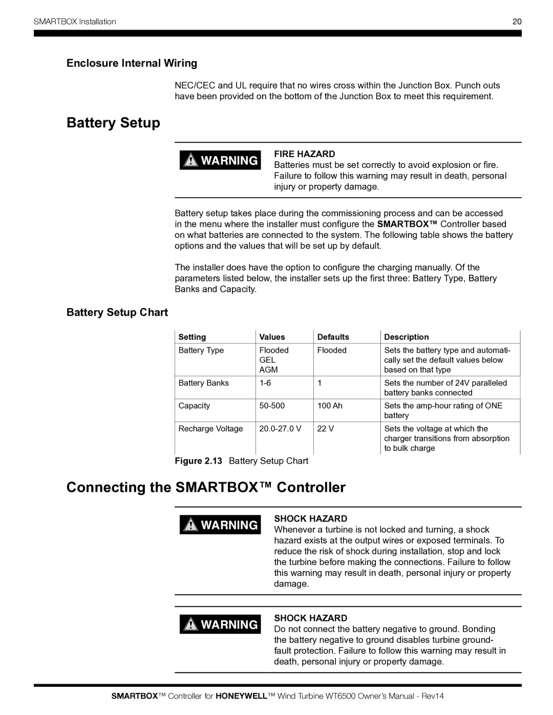
Battery setup takes place during the commissioning process and can be accessed in the menu where the installer must configure the SMARTBOX™ Controller based on what batteries are connected to the system. The following table shows the battery options and the values that will be set up by default.
The installer does have the option to configure the charging manually. Of the parameters listed below, the installer sets up the first three: Battery Type, Battery Banks and Capacity.
Battery Setup Chart
Setting | Values | Defaults | Description |
Battery Type | Flooded | Flooded | Sets the battery type and automati- |
| GEL |
| cally set the default values below |
| AGM |
| based on that type |
Battery Banks | 1 | Sets the number of 24V paralleled | |
|
|
| battery banks connected |
Capacity
100 Ah
Sets the
Recharge Voltage
22 V
Sets the voltage at which the charger transitions from absorption to bulk charge
Figure 2.13 Battery Setup Chart
Connecting the SMARTBOX™ Controller
SHOCK HAZARD
Whenever a turbine is not locked and turning, a shock hazard exists at the output wires or exposed terminals. To reduce the risk of shock during installation, stop and lock the turbine before making the connections. Failure to follow this warning may result in death, personal injury or property damage.
SHOCK HAZARD
Do not connect the battery negative to ground. Bonding the battery negative to ground disables turbine ground- fault protection. Failure to follow this warning may result in death, personal injury or property damage.
SMARTBOX™ Controller for HONEYWELL™ Wind Turbine WT6500 Owner’s Manual - Rev14