B. Sequence of Operation and Timing Charts
For details on operating modes, see "II.D.4. Operating Modes."
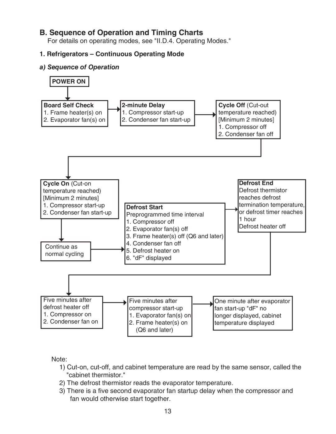
1. Refrigerators – Continuous Operating Mode
a) Sequence of Operation
POWER ON
Board Self Check
1.Frame heater(s) on
2.Evaporator fan(s) on
1.Compressor
2.Condenser fan
Cycle Off
1.Compressor off
2.Condenser fan off
Cycle On
1.Compressor
2.Condenser fan
Continue as normal cycling
Defrost Start Preprogrammed time interval
1.Compressor off
2.Evaporator fan(s) off
3.Frame heater(s) off (Q6 and later)
4.Condenser fan off
![]() 5. Defrost heater on 6. "dF" displayed
5. Defrost heater on 6. "dF" displayed
Defrost End Defrost thermistor reaches defrost termination temperature,
![]() or defrost timer reaches 1 hour
or defrost timer reaches 1 hour
Defrost heater off
Five minutes after defrost heater off
1.Compressor on
2.Condenser fan on
Five minutes after compressor
1.Evaporator fan(s) on
2.Frame heater(s) on (Q6 and later)
One minute after evaporator fan
Note:
1)
2)The defrost thermistor reads the evaporator temperature.
3)There is a five second evaporator fan startup delay when the compressor and fan would otherwise start together.
13