h.Top cover (see Top cover on page 81)
i.Speaker (see Speaker on page 86)
When replacing the system board, be sure that the following components are removed from the defective system board and installed on the replacement system board:
●SIM (see SIM on page 45)
●Memory modules (see Expansion memory module on page 48 and Primary memory module on page 70)
●WLAN module (see WLAN module on page 53)
●WWAN module (see WWAN module on page 57)
●RTC battery (see RTC battery on page 69)
●Bluetooth module cable (see Bluetooth module cable on page 87)
●Modem module (see Modem module on page 92)
●Fan/heat sink assembly (see Fan/heat sink assembly on page 93)
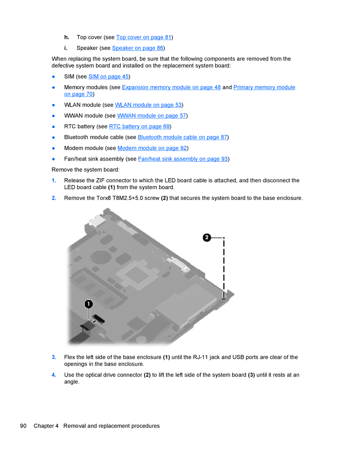
Remove the system board:
1.Release the ZIF connector to which the LED board cable is attached, and then disconnect the LED board cable (1) from the system board.
2.Remove the Torx8 T8M2.5×5.0 screw (2) that secures the system board to the base enclosure.
3.Flex the left side of the base enclosure (1) until the
4.Use the optical drive connector (2) to lift the left side of the system board (3) until it rests at an angle.
90 Chapter 4 Removal and replacement procedures