c.Switch cover and keyboard (see Switch cover and keyboard on page 65)
d.Display assembly (see Display assembly on page 72)
e.Top cover (see Top cover on page 81)
f.System board (see System board on page 89)
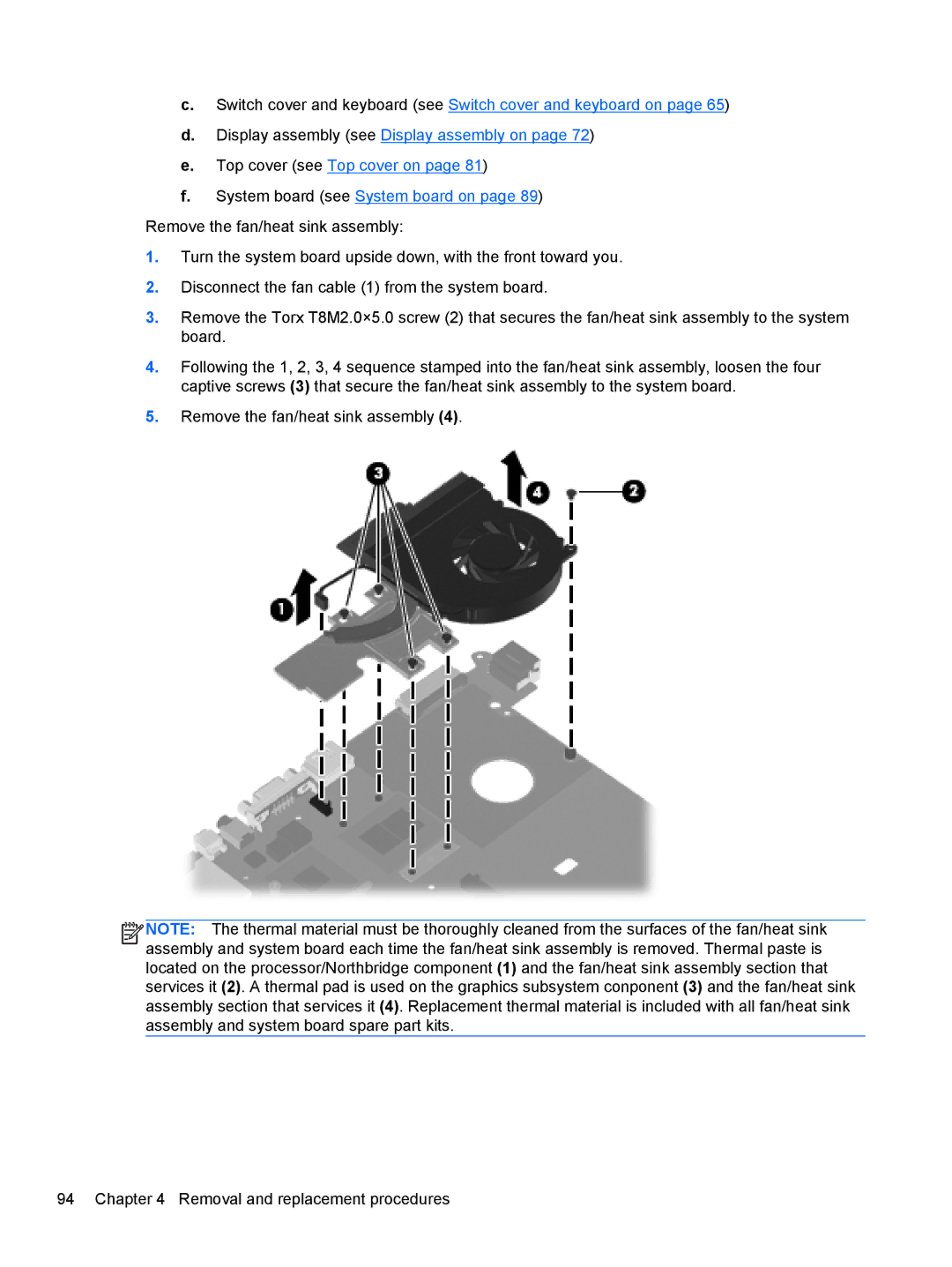
Remove the fan/heat sink assembly:
1.Turn the system board upside down, with the front toward you.
2.Disconnect the fan cable (1) from the system board.
3.Remove the Torx T8M2.0×5.0 screw (2) that secures the fan/heat sink assembly to the system board.
4.Following the 1, 2, 3, 4 sequence stamped into the fan/heat sink assembly, loosen the four captive screws (3) that secure the fan/heat sink assembly to the system board.
5.Remove the fan/heat sink assembly (4).
![]()
![]()
![]()
![]() NOTE: The thermal material must be thoroughly cleaned from the surfaces of the fan/heat sink assembly and system board each time the fan/heat sink assembly is removed. Thermal paste is located on the processor/Northbridge component (1) and the fan/heat sink assembly section that services it (2). A thermal pad is used on the graphics subsystem conponent (3) and the fan/heat sink assembly section that services it (4). Replacement thermal material is included with all fan/heat sink assembly and system board spare part kits.
NOTE: The thermal material must be thoroughly cleaned from the surfaces of the fan/heat sink assembly and system board each time the fan/heat sink assembly is removed. Thermal paste is located on the processor/Northbridge component (1) and the fan/heat sink assembly section that services it (2). A thermal pad is used on the graphics subsystem conponent (3) and the fan/heat sink assembly section that services it (4). Replacement thermal material is included with all fan/heat sink assembly and system board spare part kits.
94 Chapter 4 Removal and replacement procedures