Maintenance & Service Guide
Maintenance & Service Guide
About This Book
Iv About This Book
Table of contents
Serial ATA Sata Drive Guidelines and Features
Page
134
177
Page
Product Features
2HP Pro 3000/3010 Small Form Factor
4HP Pro 3080 Microtower
Serviceability Features
Microtower Models
Front Panel Components
1Front Panel Components
Media Card Reader Components
2Media Card Reader Components
HP Pro 3000 MT/3080 MT
Rear Panel Components
3Rear Panel Components HP Pro 3000/3080 MT
HP Pro 3010 MT
4Rear Panel Components HP Pro 3010 MT
Small Form Factor Models
5Front Panel Components
HP Pro 3000 SFF
6Rear Panel Components HP Pro 3000 SFF
HP Pro 3010 SFF
7Rear Panel Components HP Pro 3010 SFF
Installing the Operating System
Downloading Microsoft Windows Updates
Accessing Disk Image ISO Files
Installing or Upgrading Device Drivers Windows systems
Protecting the Software
HP Pro 3000/3080 Computer Setup F10 Utility
Using Computer Setup F10 Utilities
1Computer Setup F10 Utility Main Menu
Computer Setup-Main
2Computer Setup-Main
Computer Setup-Advanced
3Computer Setup-Advanced
Computer Setup-Boot
4Computer Setup-Boot
Computer Setup-Power
Computer Setup-PC Health
5Computer Setup-Power
6Computer Setup-PC Health
HP Pro 3010 Computer Setup F10 Utility
Computer Setup-Exit
7Computer Setup-Exit
Exit
8Computer Setup F10 Utility Main Menu
9Computer Setup-Main
10Computer Setup-Advanced
Supervisor Password
User Password
Sata Controller Mode
Primary Video Adapter
11Computer Setup-Power
12Computer Setup-Boot
13Computer Setup-Exit
Serial ATA Hard Drive Characteristics
Sata Hard Drives
Sata Hard Drive Cables
Sata Data Cable
Smart ATA Drives
Hard Drive Capacities
Generating Static
Electrostatic Discharge Information
Relative Humidity Event 55% 40% 10%
Preventing Electrostatic Damage to Equipment
Personal Grounding Methods and Equipment
Static Shielding Protection Levels
Method Voltage
Grounding the Work Area
Recommended Materials and Equipment
Operating Guidelines
General Cleaning Safety Precautions
Cleaning the Computer Case
Cleaning the Keyboard
Routine Care
Service Considerations
Cleaning the Monitor
Cleaning the Mouse
Power Supply Fan
Screws
Cables and Connectors
Hard Drives
Lithium Coin Cell Battery
Removal and Replacement Procedures Microtower MT Chassis
Preparation for Disassembly
Access Panel
Front Bezel
Bezel Blanks
Memory
DDR3-SDRAM DIMMs
Populating Dimm Sockets
1DIMM Socket Locations
Description Socket Color HP Pro 3000/3080 Insertion Order
Installing Memory Modules
Page
Expansion Cards
2Expansion Slot Locations HP Pro 3000/3080
7Expansion Slot Locations HP Pro
3Expansion Slot Locations HP Pro
Page
Page
Page
Cable Management
Cable Connections
Connector Name Connector Color Description
HP Pro 3000/3080
HP Pro
Drives
Drive Positions
Installing Additional Drives
System Board Drive Connections
4System Board Drive Connectors
17System Board Drive Connections HP Pro
Removing an Optical Drive
Installing an Optical Drive into the 5.25-inch Drive Bay
Removing an External 3.5-inch Drive
Installing a Drive into the 3.5-inch External Drive Bay
22Removing a 3.5-inch Device Media Card Reader Shown
Removing an Internal 3.5-inch Hard Drive
25Releasing the Hard Drive Cage Drives
Page
28Removing the Hard Drive Drives
Installing an Internal 3.5-inch Hard Drive
31Installing the Hard Drive Cage Drives
Page
Front I/O and USB Panel Housing Assembly
Power Switch/LED Assembly
System Fan
Heat sink assembly
Processor
Power Supply
Page
System Board
Battery
Type 1 Battery Holder
Type 2 Battery Holder
Type 3 Battery Holder
Page
HP/Kensington MicroSaver Security Cable Lock
Installing a Security Lock
Padlock
HP Business PC Security Lock
38Engaging the Lock Installing a Security Lock
Hood Sensor
HP Chassis Security Kit
39HP Chassis Security Kit
Preparation for Disassembly
Access Panel
Front Bezel
3Removing a Bezel Blank Bezel Blanks
Memory
Populating Dimm Sockets
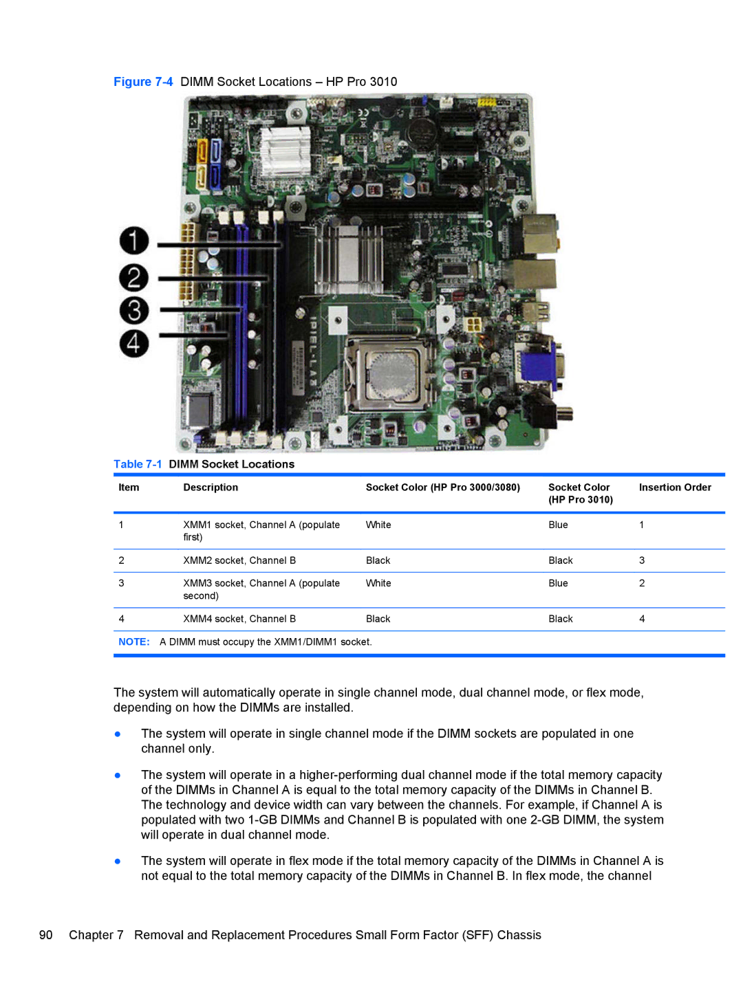
4DIMM Socket Locations HP Pro
Installing DIMMs
Page
Page
Removing or Installing an Expansion Card
8Expansion Slot Locations HP Pro 3000/3080
9Expansion Slot Locations HP Pro
Page
Page
Page
Cable Management
Cable Connections
16Drive Positions
Installing Additional Drives
System Board Drive Connectors
18System Board Drive Connectors HP Pro 3000/3080 Drives
19System Board Drive Connectors HP Pro
Removing an Optical Drive
22Removing a 5.25-inch External Drive
25Installing the Optical Drive Drives
Removing an External 3.5-inch Drive
Page
29Removing a 3.5 Device Diskette Drive Shown
Page
Page
Removing an Internal 3.5-inch Hard Drive
Page
37Installing an Internal Hard Drive Drives
Page
Plastic Wire/Cable Fastener and Clips
Page
Front I/O Device
Power Switch Assembly
Heatsink
Processor
Power Supply
Page
System Board
Battery
Type 1 Battery Holder
Type 3 Battery Holder
40Installing a Cable Lock
HP Business PC Security Lock
45Engaging the Lock Installing a Security Lock
Hood Sensor
46HP Chassis Security Kit
Connector and Icon Pin Signal
Pin Signal
Ethernet BNC
Microphone
Pin Power for CPU
Headphone
Line-in Audio
Line-out Audio
Signal Pin
Pin Power
Monitor
X1, x4, x8, and x16 PCI Express Connector Pin a Signal
PCI Express
X1, x4, x8, and x16 PCI Express Connector Pin B Signal
GND PRSNT2# Rsvd
Japanese Power Cord Requirements
General Requirements
Country-Specific Requirements
Country Accrediting Agency
Troubleshooting Without Diagnostics
Safety and Comfort Before You Call for Technical Support
Helpful Hints
Page
Solving General Problems
Table C-1Solving General Problems
Cursor will not move using the arrow keys on the keypad
Computer will not respond to USB keyboard or mouse
Cannot remove computer cover or access panel
There is no sound or sound volume is too low
Poor performance is experienced
Run Windows XP or Start Accessories Run
System does not power on
Solving Power Problems
Table C-2Solving Power Problems
Power supply shuts down intermittently
Computer powered off automatically
Solving Hard Drive Problems
Table C-3Solving Hard Drive Problems
Solving Media Card Reader Problems
Table C-4Solving Media Card Reader Problems
Boot Boot Device Priority
Computer seems to be locked up
Do not know how to remove a media card correctly
Can not write to the media card
Solving Display Problems
Table C-5Solving Display Problems
Personalization , select Adjust screen
Resolution
Blurry video or requested resolution cannot be set
Dim characters
No Connection, Check Signal Cable displays on screen
Picture is broken up, rolls, jitters, or flashes
Image is not centered
Select ImageControl/ Horizontal Position or Vertical
Clicking noise coming from inside a CRT monitor
Certain typed symbols do not appear correct
High pitched noise coming from inside a flat panel monitor
Solving Audio Problems
Table C-6Solving Audio Problems
Solving Printer Problems
Table C-7Solving Printer Problems
Printer prints garbled information
Printer will not turn on
Printer is offline
Solving Keyboard and Mouse Problems
Table C-8Solving Keyboard Problems
Table C-9Solving Mouse Problems
Select Shut Down
Solving Keyboard and Mouse Problems
Solving Hardware Installation Problems
Table C-10Solving Hardware Installation Problems
Solving Hardware Installation Problems
Solving Network Problems
Table C-11Solving Network Problems
Network status link light never flashes
Diagnostics reports a failure
Network controller stops working without apparent cause
New network card will not boot
System setup utility reports unprogrammed Eeprom
Solving Memory Problems
Table C-12Solving Memory Problems
Out of memory error
Insufficient memory error during operation
Solving CD-ROM and DVD Problems
Table C-13Solving CD-ROM and DVD Problems
Cannot eject compact disc tray-load unit
Movie will not play in the DVD drive
Recording or copying CDs is difficult or impossible
Solving USB Flash Drive Problems
Table C-14Solving USB Flash Drive Problems
Solving Front Panel Component Problems
Table C-15Solving Front Panel Component Problems
Solving Internet Access Problems
Table C-16Solving Internet Access Problems
Click on System and Maintenance
Internet takes too long to download Web sites
Double-clickAgere Systems PCI-SV92PP Soft
Modem
Table C-17Solving Software Problems
Solving Software Problems
Illegal Operation has Occurred error message is displayed
Interpreting Post Audible Codes
Beeps Meaning Recommended Action
Resetting the Password Jumper
Resetting the Cmos Jumper
Contacting Customer Support
Table D-1Specifications HP Pro 3015 Microtower
Microtower
Power Supply 115V 230V
Power Output
Heat Dissipation For 115V/60Mhz
300W 85% EFF ATX
Table D-2Specifications HP Pro 3015 Microtower
Rated Input Current maximum1
Table D-3Specifications HP Pro 3000/3080 Small Form Factor
Small Form Factor
Heat Dissipation For 115V/60Mhz For 230V/50Hz
BTU/hr 250W PFC
Table D-4Specifications HP Pro 3010 Small Form Factor
Heat Dissipation
Index
Cmos
Sata