Maintenance and Service Guide
First Edition May Document Part Number
MSG revision history
Revision Publication date Description
Iv MSG revision history
Safety warning notice
Vi Safety warning notice
Table of contents
Removal and replacement procedures
Computer Setup
Recycling
178
Xii
Product description
Panels
Chipset
Graphics
Memory
Hard drives
Optical
Drives
Diskette
Drive
Wireless
Wireless Wide Area Network
External
Media Cards
Power
Operating Preinstalled System
Keyboard
Pointing Devices
Preinstalled with Office
Restore media
Serviceability End-user replaceable parts
Web-only Support
External component identification
Windows Vista and Windows XP
Display
Component Description
Top components
Pointing devices
Lights
Buttons, switches, and speakers
Keys
Fn key
Combination with a function key or the esc key
Front components
Right-side components
Left-side components
Wireless antennas
Bottom components
Additional hardware components
Linux
Top components
Lights
Buttons, switch, and speakers
With the fn and num lk keys
Combination with a function key or the esc key
Front components
Right-side components
Left-side components
Bottom components
Wireless antennas
Additional hardware components
Service tag
Illustrated parts catalog
Computer major components
Illustrated parts catalog
Switch cover
For use only with red computers with 15.6-in HD displays
For use only with black computers with 14.0-in HD displays
For use only with red computers with 14.0-in HD displays
Speakers
Top cover
Modem module
Fan
AMD Sempron processors
Wlan module Broadcom 4322 802.11a/b/g/n Wlan modules
RTC battery
Broadcom BCM4312 802.11b/g Wlan modules
Power button board includes cable
Battery
Wwan module
Subscriber identification module SIM
Display Hinge Kit
Display assembly components
Item Description Spare part number Display bezel
Description Spare part number
Webcam module
Display Cable Kit
Display enclosure
Plastics Kit
Item Description Spare part number Plastics Kit 535780-001
Cable Kit
Description Spare part number Cable Kit
Optical drives include bezel
Mass storage devices
Item Description Spare part number
Power cords
Miscellaneous parts
Description Spare part number AC adapters
Screw Kit
Sequential part number listing
Spare part Description Number
AMD ZM, RM, QL, or SI processors
574505-001
Sequential part number listing
585220-001
That use AMD ZM, RM, QL, or SI processors
Spare part Description Number
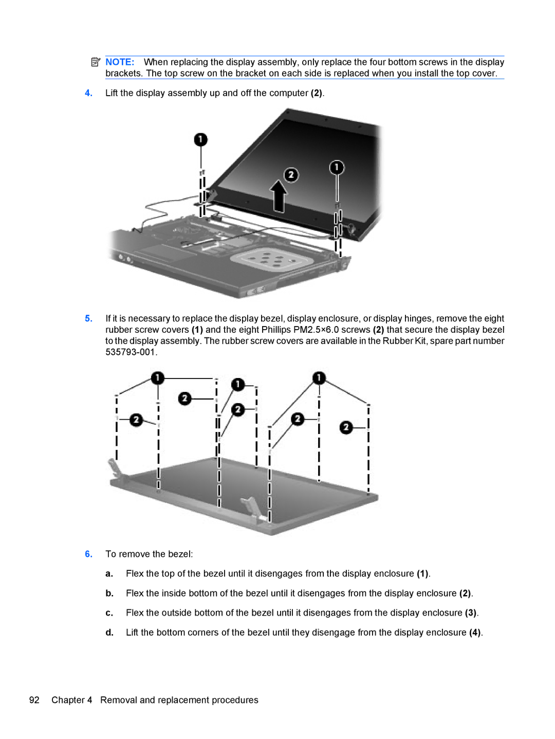
Removal and replacement procedures
Preliminary replacement requirements
Service considerations
Tools required
Cables and connectors
Drive handling
Grounding guidelines
Electrostatic discharge damage
Typical electrostatic voltage levels
Event 10% 40% 55%
Packaging and transporting guidelines
Equipment guidelines
Material Use Voltage protection level
Component replacement procedures
Service tag
Computer feet
Battery
Switch cover and keyboard
Description Spare part number Switch covers
Keyboards for use in computers with 15.6-in displays
Keyboards for use in computers with 14.0-in displays
Page
Page
Page
Memory module
Optical drive
Page
Page
Speakers
Wwan module
Palm rest
Page
Page
Hard drive
Page
Wlan module
Page
Display assembly on computers with 15.6-in displays
Page
Page
Page
Page
Page
Top cover
Page
Page
Page
Power button board
Page
RTC battery
Description Spare part number RTC battery 449137-001
Display assembly on computers with 14.0-in displays
Page
Page
Page
Page
Bluetooth module
Modem module
USB connector assembly
Page
Heat sink and fan
Page
Page
Page
Processor
AMD Sempron processor
Page
System board
Description Spare part number
Page
SIM
536599-001
Page
Computer Setup
Computer Setup in Windows Vista and Windows XP
Starting Computer Setup
Using Computer Setup
Computer Setup menus
Restoring factory settings in Computer Setup
File menu
Select To do this
Security menu
Diagnostics menu
Select
System Configuration menu
Computer Setup
Computer Setup in Linux
Using Computer Setup
Computer Setup menus
HDD Self-Test Options
System Configuration menu
Computer Setup
Specifications
Computer specifications
Wxga display specifications
Ccfl
Hard drive specifications
DVD±RW Double-Layer Combo Drive specifications
Blu-ray ROM DVD+/-RW SuperMulti DL Drive
Applicable disc Read Write
Cache buffer
DVD-ROM Drive
Applicable disc
System DMA specifications, Windows Vista and XP
System interrupt specifications, Windows Vista
Direct memory access controller
Hardware DMA System function
System interrupt specifications, Windows XP
System I/O address specifications, Windows Vista
Address hex System function shipping configuration
1003 Motherboard resources
System I/O address specifications, Windows XP
System I/O address specifications, Windows XP
System memory map specifications, Windows Vista
Memory address System function
System memory map specifications, Windows XP
E0000000-EFFFFFFF
Color Quantity Length Thread Head diameter Silver
Screw listing
Torx T8M2.5×6.0 screw
Torx T8M2.5×4.0 screw
Phillips PM2.0×2.0 screw
Color Quantity Length Thread Head diameter Black
Phillips PM2.0×3.0 screw
Page
Color Quantity Length Thread Head diameter Black
Phillips PM2.5×6.0 screw
Color Quantity Length Thread Head diameter
Phillips PM2.5×11.0 captive screw
Color Quantity Length Thread Head diameter Black 11.0 mm
Phillips PM3.0×4.0 screw
Phillips PM2.0×4.0 screw
Phillips PM2.5×3.0 screw
Page
Page
Page
Phillips PM2.5×4.5 screw
Page
Phillips PM2.5×3.0 broadhead screw
Page
Phillips PM2.5×7.0 screw
Phillips PM2.5×9.0 captive screw
Page
Backup and recovery
Backup and recovery in Windows Vista
Overview
Backing up your information
Performing a recovery
Using the Windows recovery tools
Using f11
Select Repair your computer
Backup and recovery in Windows XP
Recovering your information
Recovering the operating system and programs
Connector pin assignments
Pin Signal
Audio-in microphone
Audio-out headphone
External monitor
RJ-11 modem
RJ-45 network
Universal Serial Bus
Power cord set requirements
Requirements for all countries and regions
Requirements for specific countries and regions
Country/region Accredited agency Applicable note number
Display
Battery
Recycling
Page
Page
Page
Page
Page
Index
LAN
Page
Hdmi
SIM
DVD