Manuals
/
HP
/
Computer Equipment
/
Network Card
HP
A2969A, A3644A
manual
? L
Models:
A2969A
A3644A
1
17
55
55
Download
55 pages
53.5 Kb
14
15
16
17
18
19
20
21
Troubleshooting
Specifications
Install
Replacing the Term Power Fuse
Service Information
Set Scsi Adapter DIP Switches
Page 17
Image 17
u
n
l? L
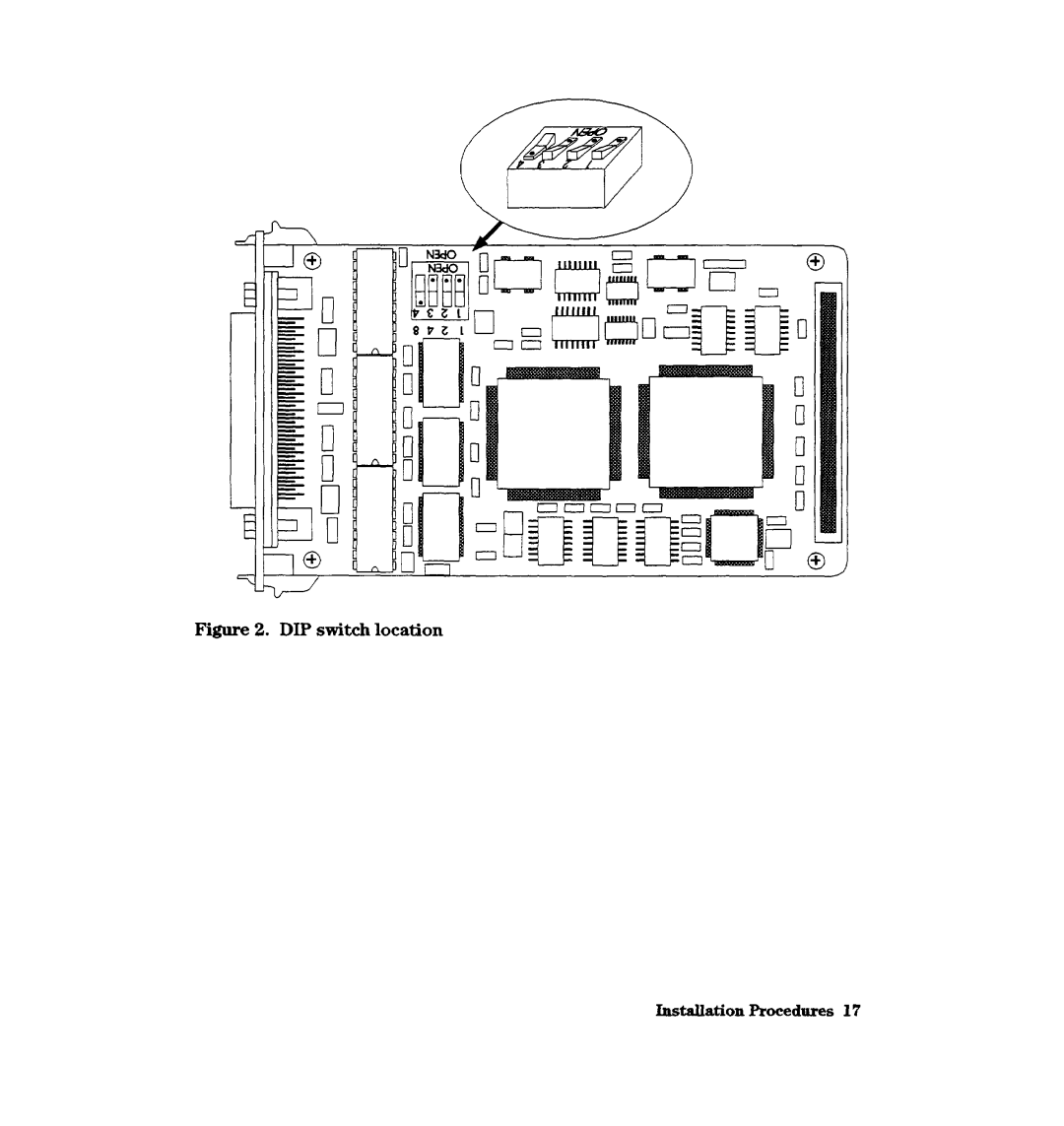
Figure 2. DIP switch location
InstsUation Procedures 17
Page 16
Page 18
Page 17
Image 17
Page 16
Page 18
Contents
III’ A2969NA36M HP-HSC FastlWide Diffkrentid Scsi Adapt,ers
Edition March
Regulatory Statements
About This Book
Table of Contents
Service Information
Reference
Description
Product Contents
HP-HSC Fast/Wide Differential Scsi A2969AX
Scsi Termhator Al65862024
Supported HP A2969A
Specifications
Power 75 W @ 5.OV Consumptior
15%to 84E-G 15%to 95%
5C to 40C 4oc to 70C 41*F to 104F
At 40C 104F
Km 15,000 ft
Installation Procedures
Installation Overview
Verify Product Contents
Prepare to Install the Adapter
Record Adapter Information
Shut Down the Operating System and Switch Off the Computer
Set Scsi Adapter DIP Switches
? L
Numbers on Printed-Circuit Card
If Necessary, Remove the Termination Resistors
II klldMLlRRAR rll-OPENl
Install the Adapter
Install the HP A2969A Scsi Adapter in an HP 9000 Series Kxxx
Slot covers
Installation Procedures
Install the HP A3644A Scsi Adapter in an HP 9000 Series T6xx
HP-H!3C I/O bus converter
Removing a cover blank
Installing the HP A3644A card Instalition Procedures
Page
Scsi Cable Connection
Connect Cable and Peripheral Devices
Connecting cables to the computer InstaUationAocedmes
Peripheral Device Connections
Proper operation on the Scsi bus
Terminate the Scsi Bus
Only the two ends of a Scsi bus should be terminated
Switch Power on to Peripherals, then to the Computer
Verm Operation
Configure the Operating System and the Adapter
Service Information
Field Replaceable Units
Troubleshooting Tools
Term power fuse location Service information
Replacing the Term Power Fuse
Installing a replacement fuse Selvice Information
Mapper
Iotest
Removal/Replacement Instructions
Reshipment Guidelines
44serviceInformation
Glossary
SmaUlight emitting device used to provide status information
Scsi ID
Page
Bus arbitration
Install the adapter
Installation
Verify proper operation
Index
Title Company Address City & State
Tape
Learning Products MS5668
Company
Copyright Hewlett-Packard Company A2969-96002
Top
Page
Image
Contents