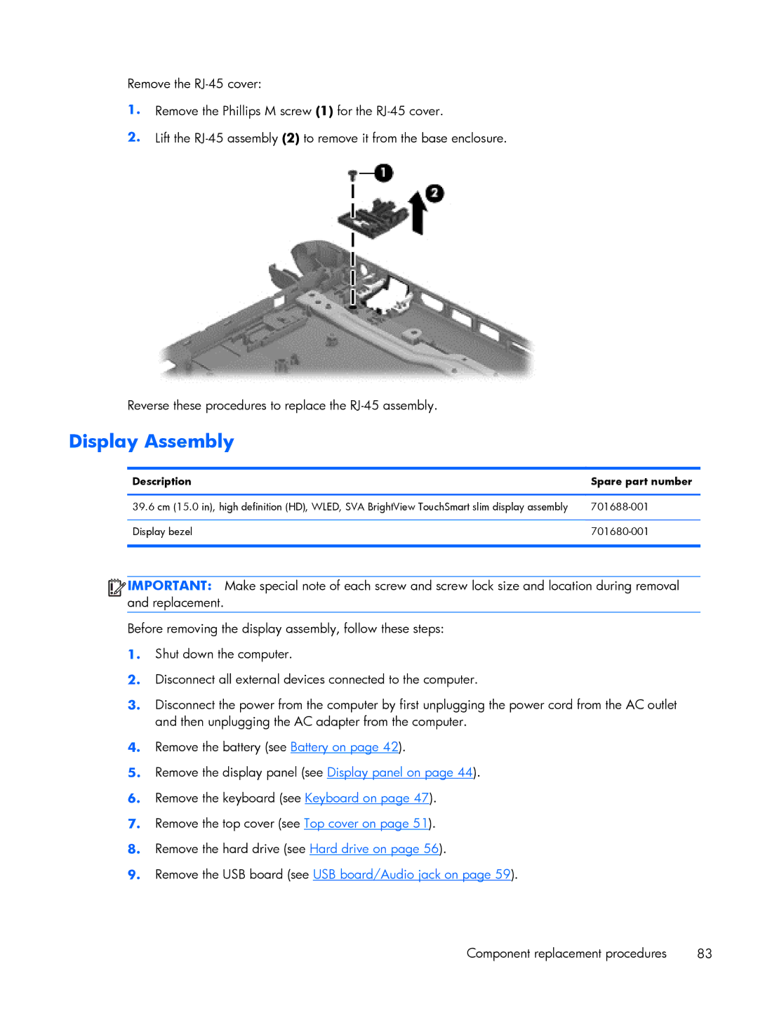
Remove the
1.Remove the Phillips M screw (1) for the
2.Lift the
Reverse these procedures to replace the
Display Assembly
Description | Spare part number |
|
|
39.6 cm (15.0 in), high definition (HD), WLED, SVA BrightView TouchSmart slim display assembly | |
|
|
Display bezel | |
|
|
![]()
![]()
![]()
![]() IMPORTANT: Make special note of each screw and screw lock size and location during removal and replacement.
IMPORTANT: Make special note of each screw and screw lock size and location during removal and replacement.
Before removing the display assembly, follow these steps:
1.Shut down the computer.
2.Disconnect all external devices connected to the computer.
3.Disconnect the power from the computer by first unplugging the power cord from the AC outlet and then unplugging the AC adapter from the computer.
4.Remove the battery (see Battery on page 42).
5.Remove the display panel (see Display panel on page 44).
6.Remove the keyboard (see Keyboard on page 47).
7.Remove the top cover (see Top cover on page 51).
8.Remove the hard drive (see Hard drive on page 56).
9.Remove the USB board (see USB board/Audio jack on page 59).
Component replacement procedures | 83 |