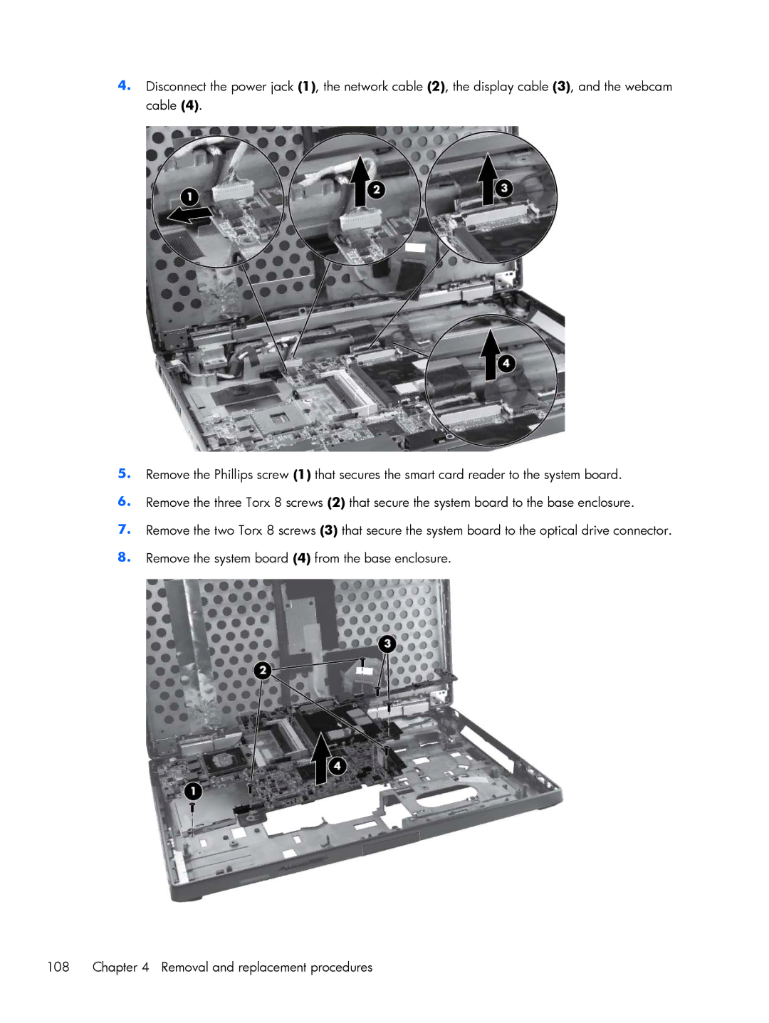
4.Disconnect the power jack (1), the network cable (2), the display cable (3), and the webcam cable (4).
5.Remove the Phillips screw (1) that secures the smart card reader to the system board.
6.Remove the three Torx 8 screws (2) that secure the system board to the base enclosure.
7.Remove the two Torx 8 screws (3) that secure the system board to the optical drive connector.
8.Remove the system board (4) from the base enclosure.
108 | Chapter 4 Removal and replacement procedures |