![]() NOTE: Steps 5 and 6 apply to computer models equipped with an Intel processor. See steps 3 and 4 for fan and heat sink removal information for computer models equipped with an
NOTE: Steps 5 and 6 apply to computer models equipped with an Intel processor. See steps 3 and 4 for fan and heat sink removal information for computer models equipped with an
AMD processor.
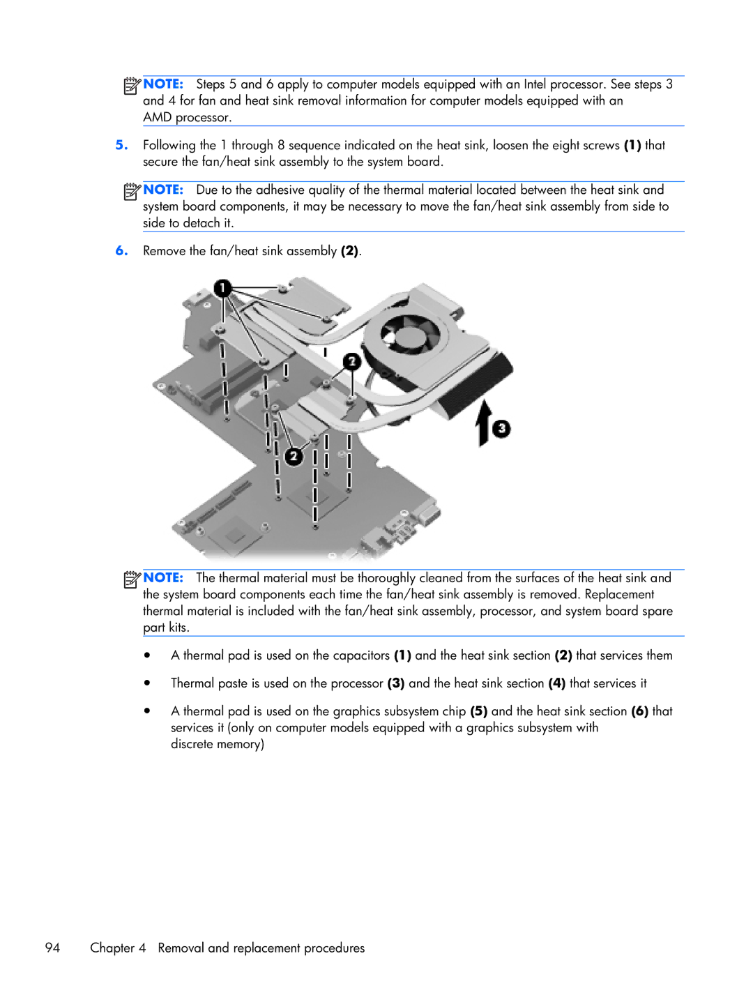
5.Following the 1 through 8 sequence indicated on the heat sink, loosen the eight screws (1) that secure the fan/heat sink assembly to the system board.
![]() NOTE: Due to the adhesive quality of the thermal material located between the heat sink and system board components, it may be necessary to move the fan/heat sink assembly from side to side to detach it.
NOTE: Due to the adhesive quality of the thermal material located between the heat sink and system board components, it may be necessary to move the fan/heat sink assembly from side to side to detach it.
6.Remove the fan/heat sink assembly (2).
![]() NOTE: The thermal material must be thoroughly cleaned from the surfaces of the heat sink and the system board components each time the fan/heat sink assembly is removed. Replacement thermal material is included with the fan/heat sink assembly, processor, and system board spare part kits.
NOTE: The thermal material must be thoroughly cleaned from the surfaces of the heat sink and the system board components each time the fan/heat sink assembly is removed. Replacement thermal material is included with the fan/heat sink assembly, processor, and system board spare part kits.
●A thermal pad is used on the capacitors (1) and the heat sink section (2) that services them
●Thermal paste is used on the processor (3) and the heat sink section (4) that services it
●A thermal pad is used on the graphics subsystem chip (5) and the heat sink section (6) that services it (only on computer models equipped with a graphics subsystem with
discrete memory)
94 | Chapter 4 Removal and replacement procedures |